Cranks -- Center Clamp
A center-clamp crank was described by Nick Abercrombie Andrews in
1994 [And94].
More recently,
(as early as 2004), Lightning center-clamp cranks
were used for RAAM,
and the center-clamp ``Negative Mass'' crank was prototyped
and pictures posted to their web site.
(see
www.negmass.com as of 2004/01).
Yet more recently (2006/05) Campagnolo and Specialized have introduced
center-clamp cranks for production.
From Negative Mass:
|
- 8mm, Titanium Coupling Bolt
- Ceramic, Silicon Nitride Ball Bearings
- 52-100 Steel, Inner Cup, Hardened to R55+, Hard Coated with Titanium
Aluminum Nitride to R90+
- 52-100 Steel, Outer Cup, Hardened to R55+, Hard Coated with Titanium
Aluminum Nitride to R90+
- Interference Coupling 17-4 PH age hardened to R45+
- Teflon Garter Seals, With Stainless Steel Springs
- Titanium 6AI 4V, Pedal Insert
- Titanium Cap, laser Etch Logo and Website
- Outer Layers, Carbon Tracer Weave. Inner Layers, Straight Tow Carbon
and Glass
- Note: Bottom Bracket has been Eliminated and Crank Axle is One with
Crank Arm
- Views of Crankset
- Detail of Coupling and Components
|
This note focuses on one area of concern:
the center bolt appears undersizd to reliably take the load.
See also end notes about some other failure modes,
the crank described in Human Power,
and the Campagnolo crank.
Bending Moment Analysis
First, consider a simple bar with a force applied at the right end,
and two pivots (shown as squares) supporting it near the left end.
If the right part of the bar is x units long and the force at
the right is F, then the torque about the middle pivot is
Fx.
A balancing force on the right
must exert an opposite torque equal to the torque from the right.
The force at the left acts at half the distance,
so the left-hand force must be double: 2F,
since (2F)(0.5x) = Fx.
As an aside, note the force on the middle pivot is the sum of
the left and right forces, or 3F.
![[split-line.jpg]](0.5-split-line.jpg)
The above figure also shows the bending moment along the
bar. The bending moment is zero at each end and highest at the middle pivot.
Since there are no other forces acting on the bar, the bending moment
changes linearly along the bar.
For example, half-way between the left and middle pivots,
the bending moment is half of the highest bending moment.
The bending moment tells us how much load is within the bar.
Suppose we put a hinge in the bar someplace:
the bar would tend to fold at the hinge.
Now suppose we grabbed either side of the hinge and tried to
keep the bar from folding. How hard would we have to twist the hinge
in order to keep it from folding?
In the above diagram suppose we put a hinge (shown as a dot)
half-way between the left and the middle.
From the bending moment diagram, we see the bending moment is half
what it is at the middle pivot.
The bending moment at the middle is Fx,
so the bending moment at the hinge is 0.5Fx.
We call this (1) and will return to it shortly.
The above analysis assumes the force is on one end of the bar,
which models a rider pressing on one pedal.
If the rider presses on both pedals (as with landing from airborne),
the analysis is similar -- superimpose a left bending moment on the
right bending moment to get the total moment.
If, for example, the left and right forces are both F/2,
then the moment between the bearings is constant at 0.5Fx.
Now suppose the lever is replaced with a crank spindle,
as shown below.
The layout and the load are the same as the bar.
If the crank spindle is split in the middle,
then we want to know what we have to do to keep it
from falling apart under load.
![[split-spindle.jpg]](0.5-split-spindle.jpg)
The joint is bolted together.
When no bending moment is applied (e.g., there is no load F),
a bolt clamping force B is distributed between the two sides,
causing an opposite spreading force of 0.5B on the top and
bottom.
The maximum moment the joint can support is when
the spreading force on the top goes to zero and the spreading force on
the bottom is equal the bolt clamping force.
If a larger moment is applied, then the top will separate (joint
failure).
How much moment is supported by the joint at the maximum moment?
If the top and bottom are each a distance y from the bolt,
then the moment which is supported is By.
In practice, the spindle is really a 3-dimensional object,
so the bolt force is distributed all around the spindle, not just
to the top and bottom.
Thus, results from the simple model are optimistic.
The real joint probably requires double the bolt force
to hold a given load,
because the side regions of the spindle oppose the bolt compression,
but contribute little to resisting the bending load.
Thus, the moment which is supported is 0.5By.
This observation is noted (2); we will return to it shortly.
We know from (1) that the bending moment from the load is 0.5Fx.
The joint moment must equal the load moment in order for the joint to
stay togeter.
Thus, 0.5By = 0.5Fx, or just
By = Fx.
If the distance y is 0.125x,
then we can replace y in the equation, giving
0.125B = Fx, or
B = 8F.
We call this (3).
It may appear that we can reduce the clamp load by moving the split left.
That does indeed reduce the joint load when standing on the right pedal.
However, it increases the joint load when standing on the left pedal.
Thus the best you can do is to put the split at the center
of the load.
(The right-side load is higher due to chain tension,
so the center of the load is not the center of the crank.)
Bending Moment Application
Suppose the distance x is the distance from the
spindle bearing to the center of the pedal, and is 96mm,
which is close to typical;
that the distance between bearings is half that, or 48mm,
which is also close to typical;
and that the spindle is half that, or 24mm in diameter,
which is much thicker than square-taper cranks, but only slightly
thicker than Octalink(tm) and Isis(tm) spindles,
similar to Bullseye(tm),
and smaller than some Coda(tm) and newer Shimano spindles.
Thus, these dimensions are plausible.
Riders periodically load a pedal with about twice their body
weight.
These loads occur from pulling on the handlebars
while climbing,
and also from shock loads such as rough roads and airborne landings.
Typical heavy riders weigh about 100kgf and some riders
weigh 200kgf.
Doubling the lower figure (i.e., the joint is only suited
to lighter riders) gives 200kgf pedal load.
By (3), the bolt has to be tightened to 8 times the pedal
load, or 1600kgf.
An 8mm grade 8 (high-strength) bolt has a yield (breaking) strength
of about 3200kgf (check); a 10mm grade 8 bolt has a yield strength of about
5000kgf (check).
The grade 8 bolt may seem ``more than enough'',
but be aware that there are additional design issues.
For example, bolts can fatigue,
leading to failure without ever being loaded to the rated load.
Note that the ``Negative Mass'' crankset uses an 8mm Titanium bolt,
which has substantially less strength than the above steel bolt,
probably less than half.
The above equations can be generalized for arbitrary
combinations of offset, bearing spacing, joint position, etc.
Torque Transmission
The crank spindle joint carries torque.
Thus, the spindle halves are not simply flat faces.
Instead, they are engaging teeth, as shown in the figure below.
![[split-detail.jpg]](0.5-split-detail.jpg)
The spindle gets an alternating torque load:
If you stand on the pedals with your right foot forward,
the joint is twisted one way.
If you stand left foot forwrd, the joint is twisted the other.
Since the spindle gets an alternating load,
the engaging teeth cannot be parallel.
Consider a joint with parallel teeth which is loose:
the alternating twisting load will make the joint
work back and forth.
Whatever part of the joint takes an axial load will rub,
causing it to wear and fail.
![[split-parallel.jpg]](0.5-split-parallel.jpg)
It might seem that motion can be avoided if the
tooth dimensions are chosen so there are no gaps
between the two parts -- called a ``press fit'' or
an ``interference fit''.
Consider, however, a loose press fit.
That is, the parts are in contact, but just barely.
The material of the joint is slightly flexible (``elastic'').
As torque is applied, the faces under load will
compress slightly, and the unloaded faces will separate slightly.
When the torque is released, the loaded faces will spring back
and the unloaded faces will be pushed back in to contact.
Although the motions are small, the continual rubbing will cause wear,
thus causing the joint to fail.
A very tight fit may reduce motion,
but requires expensive high precision manufacturing.
Also, a tight fit is sensitive to wear,
corrosion, and other things which change the dimensions.
For example, assembling and disassembling the joint several times
may cause a tight press fit to turn in to a loose press fit,
which then fails under load.
For these reasons, the spline tooth faces are not parallel.
However, with non-parallel faces, torque in the joint causes a
force which tends to separate the joint.
The separating force is an extra load which is carried by the bolt,
and peak torque may occur at the same time
as peak pedal load (bending moment).
Torque Transmission II
When torque is applied, the teeth are cantilevered (overhung) and
thus bend slightly under load.
At the same time load is increased on one face it is reduced on the
other.
Each tooth is thus loaded in a way that tends to cause slight relative
motion in the the unloaded faces.
Motion leads to fretting joint damage.
Higher preload should reduce motion and thus damage,
but requires heavier construction.
It is not clear what is the range of loads which damage
the various existing designs.
Other Notes
Bolt motion
The bolt which holds the joint is likely to loosen in use.
The material of the joint is slightly flexible.
As pedaling torque is applied and released,
there will be twisting between the area that supports the bolt
head and the area with the bolt threads.
The motion occurs because the material is not
perfectly stiff and bends under load.
The twisting motion in the axle causes a varying twist on the bolt.
Repeated twisting can cause fatigue,
though the axle is sufficiently stiff that fatigue is unlikely.
Twisting can also cause the bolt threads to ``creep''.
When the twist is one way, it tries to tighten the bolt,
but the ramp of the threads tends to resist tightening.
When the twist is the other way, it tries to loosen the bolt,
and the ramp of the threads tends to help loosening.
(The bolt tension times the sin of the thread angle is
the inherent unscrewing force.)
If the friction in the bolt threads is too low,
the bolt can ``creep'' and gradually loosen.
The bolt should therefore have a very high preload
and/or a mechanical lock.
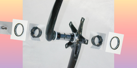
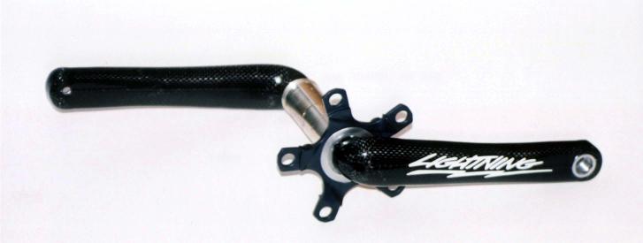
Andrews' Crank
A center-clamp crank was built by Nick Abercrombie Andrews in 1993
and shown in the Spring/Summer 1994 issue of
the IHPVA's Human Power magazine [And94].
The Andrews crank uses a threaded sleeve instead of a bolt.
The sleeve has left-hand and right-hand threads.
The opposing threads act like a turnbuckle.
Turning the sleeve one way clamps the joint;
turning it the other forces the joint apart.
![[sleeve-spindle.jpg]](0.5-sleeve-spindle.jpg)
![[X]](andrews01.quarter.jpg)
![[X]](andrews02.quarter.jpg)
More recent center-clamp cranks (Negative Mass; Campagnolo)
are nearly identical except the use of a bolt instead of a sleeve
changes clamp operation slightly:
A sleeve has more and better-placed material to carry clamping
force. Thus, for a given weight, bolted joint
will have lower preload and thus lower carrying capacity.
Accesss to the clamp is problematic --
how do you put a wrench on a sleeve which is inside the bottom
bracket shell but outside the hollow spindle?
Andrews drilled a hole in the
bottom bracket shell; installing a bolt holds the sleeve
while tigtening or loosening the joint by spinning the cranks.
A bolted joint fits without modification.
External threads on the spindle
are at the largest diameter and thus at increased
risk for fatigue from bending loads.
However, note that bolt threads are at much higher load
than sleeve threads, which may increase fatigue on bolt threads.
As with the Negative Mass design, there is no locking mechanism
to keep the sleeve from unscrewing (creeping) under cyclic torque
load.
Internal-Sleeve Clamp
Another design variation uses an internal sleeve.
This is similar in principle to using a bolt,
but the ``bolt'' material is better-placed --
closer to the spindle diameter than a bolt, which is closer to half the
spindle diameter (y = 0.25x rather than y = 0.125x as shown in the 2nd diagram.)
Campagnolo
From
www.campyonly.com
(summarizing):
called ``Ultra-Torque'',
for several 2007 Campagnolo groups.
The call it a ``Hirth'' joint after the gasoline engine crankshaft
by Hirth assembled in pieces using a similar joint.
The clamp screw preloads the joint to at least 500kgf.
They also note the elbow can be relatively flat,
compensating for increased bottom bracket width
due to using outboard bearings.
The use of outboard bearings and relatively thick axle should
reduce center bolt loads.
For example, suppose the pedal load is applied 45mm outboard of the
bearing; that the bearings are 75mm apart; the spindle is 25mm
in diameter; and the bolt load is applied at the center.
The bending moment at the bearing is F*45mm;
the bending moment at the center clamp is F*22.5mm.
The clamp force needed at half the spindle diameter is F*22.5/12.5 =
F*1.8,
which is dramatically lower than (3).
From
www.cyclingnews.com
(see also here)
as of 2006/05/19:
![[X]](CampagnoloUltraTorque1.jpg)
![[X]](CampagnoloUltraTorque2.jpg)
![[X]](CampagnoloUltraTorque3.jpg)
The center bolt is rated 42 Nm torque
(from
http://www.cyclingnews.com/tech.php?id=/photos/tech/features/campaggroups2007/gallery-campggroups2007 as of 2006/07/19):
![[© Campagnolo]](picture9.jpg)
![[© Campagnolo]](picture10.jpg)
We estimate the center clamp force:
Suppose the bolt is 15mm diameter, has a 1mm pitch thread, is
tightened to 42 Nm and has no thread friction.
With a circumference of 15mm * pi = 47mm, the slope of the thread is
about 1:47, so (small angle approximation)
for each Newton along the threads there should be about 47 Newtons
across the threads.
Tightened to 42 Nm and diameter 15mm, there should be about
4200 Nmm / 15mm = 280 N along the threads. 280 * 47 = 13,160 N
or 13,160/9.8 = 1340 kgf.
Using the 1.8*F figure computed above gives 1340/1.8 = 750kgf
pedal load before joint failure.
Estimating riders apply about double their weight to the pedal,
this gives a rider weight limit around 325kgf,
well in excess of normal riders.
That suggests the Campagnolo center-bolt crank will not be prone to
joint failures.
Other sources report different preloads. One says 500kgf.
http://www.bikemania.biz/2007_Campagnolo_Chorus_10_Speed_Crankset_p/campy_choruscrankset_2007.htm
(as of 2007/03/01) says 600kgf.
Using the 1.8*F figure gives either 500kgf/1.8 = 275kgf pedal force
or 600kgf/1.8 = 330kgf pedal force.
One common estimate (but not based on measurement) is the peak common
pedal forces are about 2x to 2.5x rider weight.
These figures would give from 110kgf to 165kgf rider weight limits.
The lower number is in the range of common rider weights,
suggesting that proper bolt tightening is very important
to avoid joint failures.
As a secondary problem, it is plausible the bolt will tend to
self-unscrew as the ends of the bolts are twisted under pedaling load.
Whether that is a problem depends on the stiffness of the joint
and the applied loads; and is beyond the analysis here.
The Andrews crank uses a double-threaded fastener, so when the
fastener is unscrewed, it forces apart the two crank pieces. The
approach allows use of teeth with faces which are nearly axial, but
disassembly does not require special tools.
The Campagnolo bolt is neither double-threaded nor retained. Thus,
face angles which are nearly axial would lead to a crank which could
be difficult to disassemble even when the bolt is loose or
removed.
Near-axial faces are close to a spline, but without the torque
transmission issues discussed above.
Using a spline means that pushing hard on the left pedal can
transmit torque without creating a force which tends to separate the
two crank parts.
As the face angle is more and more off-axial, pedaling torque
leads to a separating force. Bolt loads introduced via torque can
reduce the effective tension available to keep the two halves
clamped.
Thus, there is a design tradeoff between tooth angle and
disassembly.
Another choice is asymmetric teeth, which generate less separating
force under forward pedaling, but more separating force under
back-pedaling. Such a design may be a good match to typical pedaling
loads.
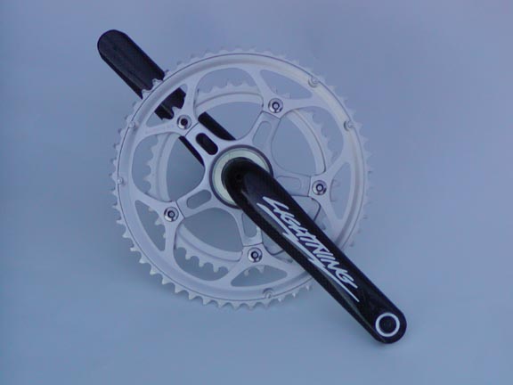
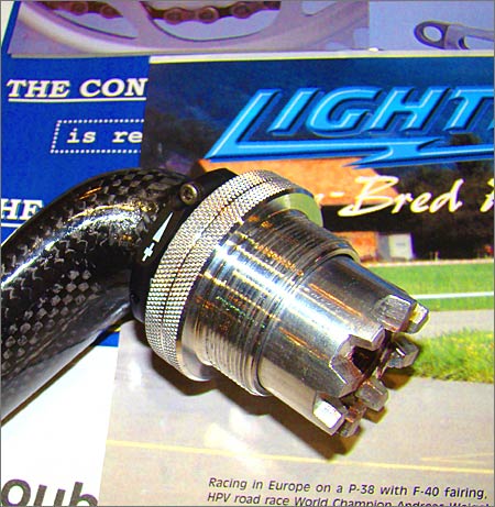
Ligtning
cranks were used as early as 2004 RAAM.
and as of 2008 are offered for sale.
Rated 425g with carbon 2-chainring spider, 460g with aluminum
3-chainring spider. Lengths 165mm to 180mm.
250 pounds rider weight limit.
Patented.
Pez
Cycling News (as of 2012/09) said "[...] 570 grams with rings for a
(53-39) double [...] the designer holds the patent for an integrated
crank design used by Specialized [...]".
The Lightning is also available with a spacear that "grows" it from a
68 mm BB shell to a 73 mm shell.
![[541145d1273072984-lightning-carbon-cranks-light-center68-73.jpg]](fcdn.mtbr.com/attachments/weight-weenies/541145d1273072984-lightning-carbon-cranks-light-center68-73.jpg)
![[541143d1273072655-lightning-carbon-cranks-light-73-spacer-8.jpg]](fcdn.mtbr.com/attachments/weight-weenies/541143d1273072655-lightning-carbon-cranks-light-73-spacer-8.jpg)
(Via mtbr.com as of 2013/07.)
Racycle
The Racycle was produced from about 1896 to the early
1920s [RC09a]. From 1896 to 1910, many
Raycycle models used a center-clamp crank design with many
similarities to recent center-clamp
cranks [RC09b]:
![[1908Catalog6_A.jpg]](3.bp.blogspot.com/_9tq2Rh0MMc8/SXbX9gmcXFI/AAAAAAAAACg/1T_T1R79Zlc/s1600/1908Catalog6_A.jpg)
Like other center-clamp designs, the cranks are each half-width and
have castellations drawn together by a center bolt. Unlike other
designs, the the "cone sleeve" is a hollow axle that reaches nearly
the full width of the bottom bracket. The cone sleeve has bearing
races and remains in the bottom bracket when the cranks are
removed.
In other center-clamp cranks described here, axle bending loads are
carried by the face of the center clamp;
see above under "Bending Moment Analysis"
In the Racycle crank, loads may be carried the same way, but if the
axle bends far enough it will transfer significant bending load
through the cone sleeve. As a "reducto ad absurdum", consider
removing the left crank and then standing on the right pedal: the two
ends of the half-axle will rest on the cone sleeve, and will do so
through the entire pedal stroke. With other center-clamp cranks,
removing the left arm and standing on the right pedal would put
the bending load on the right bearing (and probably destroy it).
The lock nut suggests that despite the cone sleeve support there was
still substantial motion in the joint, causing the connecting bolt to
unscrew.
Racycles were popular and durable enough that 100+ years later there
are still many working examples.
As a side note, the center-clamp Racycle was apparently built in at
least two models. The drawing above shows a later model with bearings
cups connected via a threaded sleeve; the entire assembly is held by a
slotted bottom bracket with pinch bolts. An earlier model, perhaps
1896-1900, threads in to a bottom bracket and anticipates the Magic
Motorcycle cantilevered "external" bottom bracket.
Specialized
The specialized crank uses a large-diameter aluminum spindle and an
oversize (nonstandard) shell. The larger spindle should help leverage,
but the fixing bolt size is unknown (the visible 6mm hex is reportedly
a dust cap).
When joint motion occurs, aluminum may wear more quickly.
Rubbing aluminum creates aluminum oxide wear particles which are
highly abrasive and may lead to accellerated wear and/or stress
fractures.
This may accellerate joint failure even if joint motion is rare.
From
http://www.velonews.com/tour2005/tech/articles/8447.0.html
as of 2006/05:
It appears a newer version uses a much finer tooth pitch.
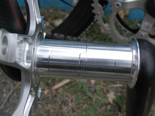
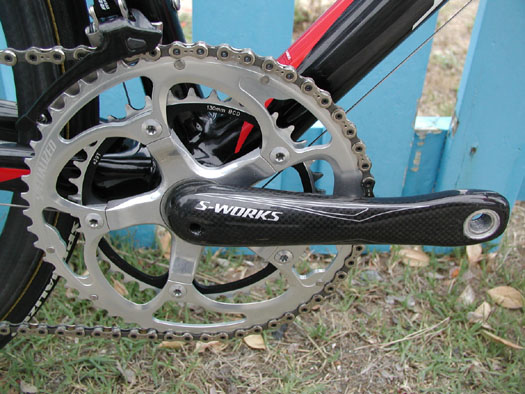
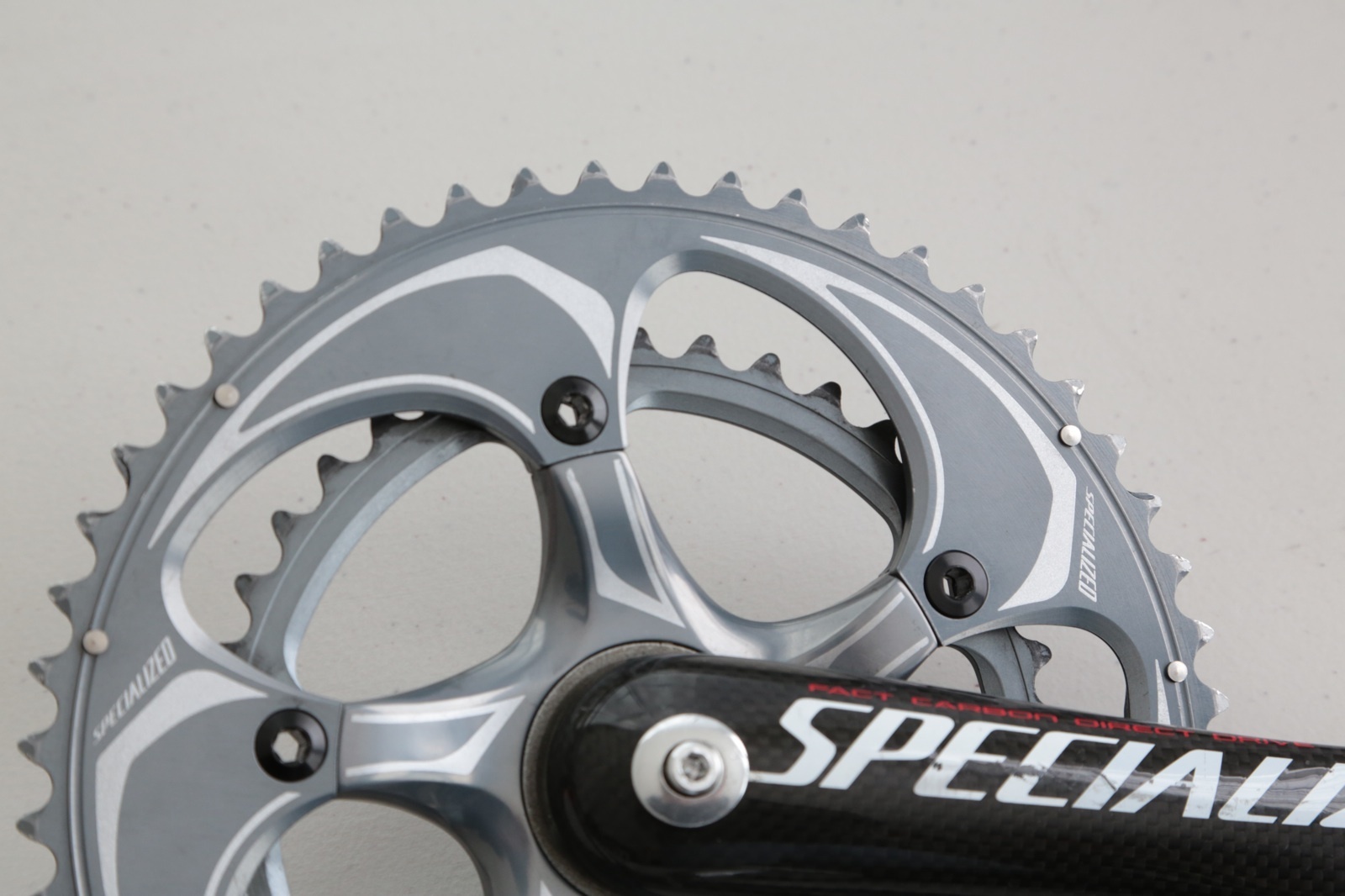
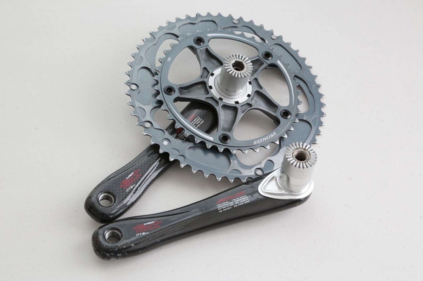
Photos from eBay auction 325652531304 as of 2024/05, a Specialized
"FACT" crank:
![[s-l1600.jpg]](img/i.ebayimg.com/images/g/9ewAAOSwKQRkOLfV/s-l1600.jpg)
![[s-l1600.jpg]](img/i.ebayimg.com/images/g/UYsAAOSw9IFkOLfW/s-l1600.jpg)
![[s-l1600.jpg]](img/i.ebayimg.com/images/g/GiEAAOSwhIRkOLfX/s-l1600.jpg)
![[s-l1600.jpg]](img/i.ebayimg.com/images/g/vmkAAOSwyXVkOLfX/s-l1600.jpg)
Photos from eBay auction 261173138849 as of 2013/04, a Specialized S-Works
FACT crank. The first and last photos show a finer-pitch spline.
IMG,
IMG,
IMG,
IMG.)
Engineering Tradeoffs
The center-clamp crank may offer several engineering
(quantitative) benefits compared to other crank designs.
(It also offers disadvantages.)
The following considers advantages compared to a Bullseye-style
two-piece crank with one arm held by a pinch spline.
- Minimal overhang. The pinch-spline design has a clamp outside the
BB. The clamp must be of some minimum width, which is almost certainly
wider than the minimum width for an elbow.
Thus, the center-clamp crank may offer narrower pedal spacing
and/or more ankle clearance.
- Pinch-spline cranks are typically offered with a single length of
crank spindle.
Alternatively, since the spindle and arm are one piece,
making and stocking several lengths requires offering a combination of
spindle and arm lengths. For example, offering 3 spindle lengths and 5
arm lengths means making and stocking 3x5=15 different crank/axle
assemblies. A center-clamp crank may use spacers (with face splines)
between the two arm/spindle pieces, thus allowing one set of arms to be
used in several different crank axle length configurations.
- Both cylindrical splines and face splines are relatively expensive to
manufacture. But in some situations, the face splines may be
cheaper.
- When the clamp fails, a center-clamp design may be less likely to
throw you to the street than a pinch-spline crank.
References
[And94]
``A Folding MWB Two-Wheeled Recumbent'',
Nick Abercrombie Andrews.
Human Power,
spring-summer 1994,
11(2), pp. 18-21.
Human Power
is a publication of the
International Human Powered Vehicle Association (IHPVA;
www.ihpva.org).
As of 2006/05, the article is available from
http://www.ihpva.org/HParchive/PDF/37-v11n2-1994.pdf
.
[Mom04]
Patent 6,829,965,
Bruno Mombrinie,
"Two-piece bicycle crank set".
14 December 2004.
[img,
img,
img,
img,
img,
img,
img,
img,
img,
img,
img,
img,
img,
img,
img,
img,
img,
img,
img,
img,
img]
[RC09a]
"Racycle Introduction", 2009/01/15.
http://racycle.blogspot.com/2009/01/racycle-catalog-cover-1904.html
As of 2015/12:
Racycle bicycles were built by the Miami Cycle Company of Middletown,
Ohio, from 1896 to about the early 1920s, possibly as late as 1924.
[RC09b]
"How to Disassemble a Racycle crank (1896 through 1910)", 2009/01/21.
http://racycle.blogspot.com/2009/01/racycle-is-one-of-those-rare-bicycles.html
As of 2015/12:
Below are instructions directly from the Racycle catalog, in this
case 1904, but the basic procedure appears to have been the same from
1896 through 1910.
![[split-line.jpg]](split-line.jpg)
![[split-spindle.jpg]](split-spindle.jpg)
![[split-detail.jpg]](split-detail.jpg)
![[split-parallel.jpg]](split-parallel.jpg)
![[sleeve-spindle.jpg]](sleeve-spindle.jpg)
![[X]](andrews01.jpg)
![[X]](andrews02.jpg)

EBRJUpl1f3!~~60_57.JPG)