
The purpose of the crank bearing is to support loads. The primary loads are radial load from pedal pressure and chain tension. There are smaller axial loads including components of pedal pressure and chain load; also accidents, etc.
Traditional cup-and-cone crank bearings are ``backward'', thus increasing bearing loads and shortening the service life of the bearing assembly. This section describes how the loads are ``backwards''.
The following diagram shows a simple crank bearing.
If a force F acts on the end of the spindle, the load creates a radial force at each of the bearing contacts. The bearings are loaded at an angle, not radially. Thus, the radial load on the bearing causes an axial load. Using a shallower bearing contact angle causes a larger axial load.
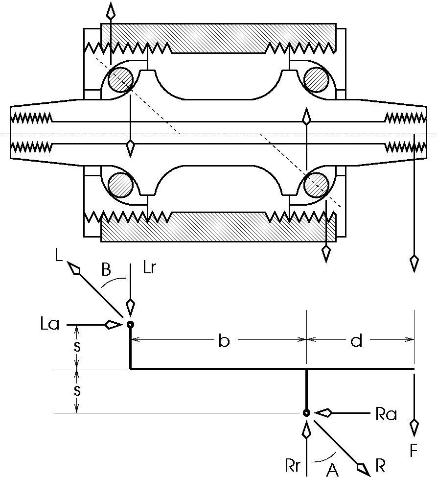
Bearing loads can be modeled as follows. First, the load F acts at distance d. It causes a torque about the right bearing of F * d. The left bearing, a distance b away opposes that torque with a torque Lr * b. However, loading the bearings causes an axial force La which causes a torque La * 2s in the same direction as the original load. Thus:
(F * d) + (La * 2s) = (Lr * b)
The radial forces must add to zero, else the spindle would be in motion. Thus, the forces pushing up in the diagram must equal the forces pushing down:
F + Lr = Rr
As long as F is the only external force, then the force La pushing to the right is equal Ra, the force pushing left. Thus, the term La * 2s could also be written (La * s) + (Lr * s), or in several other forms. At any rate:
La = Ra
At each bearing, the axial and radial forces are related by the angle of contact across the bearing. If the angle of contact is near radial, then the axial force will be small for a given radial load. If the angle of contact is near axial, then the axial force will be large for a given radial load. Thus:
La = Lr * tan(B)
Ra = Rr * tan(A)
Note that the bearings are shown in the diagram as both having a 45-degree angle. In operation, ball bearings run at different angles depending on the applied load. If the load is largely axial, the bearing will try to move to a position where the contact is more axial and less radial, as shown below in (a). Conversely, if the load is mostly radial, the bearing will try to move as shown in (b).
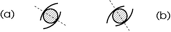
Motion of the bearings requires slop or elasticity in the overall assembly, but the motions are small and, in practice, the bearings, races, spindle, etc., are all made of slightly flexible materials. Further, note that if the spindle of the earlier figure moves slightly to the left, it both causes the left bearing to assume the position (a) and at the same time causes the right bearing to assume the position (b).
We do not know the exact bearing angles A and B, but we do know the radial forces (F + Lr = Rr) and do know the left and right axial forces are equal (La = Ra). Finally, examining wear on the spindle and cups of a bottom bracket shows the bearings run near a 45 degree angle. Thus, we can tabulate a few results.
Consider a bottom bracket with spindle contact points b 50mm apart and points 2s 15mm apart. With a pedal load of 100 kgf applied at 100mm. The load on the right bearing will be larger than the load on the left, so we are interested in the peak bearing load R, which is Rr/cos(A).
Thus,
Rr = F + Lr
Lr = [(F * d) + (La * 2s)]/b
La = Ra = Rr * tan(A)
Substituting,
Rr = F + [(F * d) + ([Rr * tan(A)] * 2s)]/b
Simplifying,
(Rr * b) = (F * b) + (F * d) + ([Rr * tan(A)] * 2s)
(Rr * b) - ([Rr * tan(A)] * 2s) = (F * b) + (F * d)
Rr * (b - [2s * tan(A)]) = F * (b + d)
Rr = F * (b + d) / (b - [2s * tan(A)])
Tabulating for some values of A:
| F | d | b | 2s | B | Lr | L | A | Rr | R | ||
|---|---|---|---|---|---|---|---|---|---|---|---|
| 100 kgf | 100 mm | 50 mm | 15 mm | 0 deg | 200 kgf | 200 kgf | 0 deg | 300 kgf | 300 kgf | ||
| 100 kgf | 100 mm | 50 mm | 15 mm | 7 deg | 208 kgf | 210 kgf | 5 deg | 308 kgf | 309 kgf | ||
| 100 kgf | 100 mm | 50 mm | 15 mm | 14 deg | 217 kgf | 224 kgf | 10 deg | 317 kgf | 322 kgf | ||
| 100 kgf | 100 mm | 50 mm | 15 mm | 20 deg | 226 kgf | 241 kgf | 15 deg | 326 kgf | 338 kgf | ||
| 100 kgf | 100 mm | 50 mm | 15 mm | 26 deg | 237 kgf | 263 kgf | 20 deg | 337 kgf | 358 kgf | ||
| 100 kgf | 100 mm | 50 mm | 15 mm | 31 deg | 249 kgf | 289 kgf | 25 deg | 349 kgf | 385 kgf | ||
| 100 kgf | 100 mm | 50 mm | 15 mm | 35 deg | 263 kgf | 319 kgf | 30 deg | 363 kgf | 419 kgf | ||
| 100 kgf | 100 mm | 50 mm | 15 mm | 38 deg | 280 kgf | 355 kgf | 35 deg | 380 kgf | 464 kgf | ||
| 100 kgf | 100 mm | 50 mm | 15 mm | 41 deg | 301 kgf | 396 kgf | 40 deg | 401 kgf | 523 kgf | ||
| 100 kgf | 100 mm | 50 mm | 15 mm | 43 deg | 329 kgf | 447 kgf | 45 deg | 429 kgf | 606 kgf | ||
| 100 kgf | 100 mm | 50 mm | 15 mm | 44 deg | 367 kgf | 512 kgf | 50 deg | 467 kgf | 726 kgf | ||
| 100 kgf | 100 mm | 50 mm | 15 mm | 45 deg | 425 kgf | 604 kgf | 55 deg | 525 kgf | 915 kgf | ||
| 100 kgf | 100 mm | 50 mm | 15 mm | 46 deg | 524 kgf | 753 kgf | 60 deg | 624 kgf | 1249 kgf | ||
| 100 kgf | 100 mm | 50 mm | 15 mm | 46 deg | 741 kgf | 1063 kgf | 65 deg | 841 kgf | 1990 kgf | ||
| 100 kgf | 100 mm | 50 mm | 15 mm | 45 deg | 1607 kgf | 2270 kgf | 70 deg | 1707 kgf | 4991 kgf | ||
| 100 kgf | 100 mm | 50 mm | 15 mm | 43 deg | -2608 kgf | 3560 kgf | 75 deg | -2508 kgf | -9690 kgf | ||
| 100 kgf | 100 mm | 50 mm | 15 mm | 39 deg | -528 kgf | 675 kgf | 80 deg | -428 kgf | -2463 kgf | ||
| 100 kgf | 100 mm | 50 mm | 15 mm | 29 deg | -224 kgf | 255 kgf | 85 deg | -124 kgf | -1417 kgf |
Note first that a radial bearing -- where the angle A is near zero -- has a very small bearing load. Radial bearings are discussed below.
Note also that as the angle A gets past about 50 degrees, the bearing force R skyrockets. By 75 degrees the equation shows bearing forces have gone negative. In practice, bearing forces cannot go negative. What happens is a small applied radial load causes a large axial force, and the large axial force ``aids and abets'' the original force to such a degree the bearing is no longer able to support the applied load.
As noted above, as the radial load increases, the bearing configuration tends to change so the right bearing is ``more radial'' (smaller angels of A).
The bearing angle and the amount by which the bearing moves depends in part on how tight the bearing is to start. If the bearing is adjusted tight, the bearing angles will remain high. If the bearing is adjusted loose, the bearing angles will go low, so most of the load is carried radially.
Unfortunately, this presents us with a conundrum: both theory and practice of bearings shows that, all else equal, a bearing works better if it is initially tight [1]. Here, ``works better'' means either that the bearing can carry more load, or it lasts longer (is more durable) when carrying a given load. The reason is that bearing preload helps to ensure the load is carried by more balls. Although preload increases the total bearing forces, it decreases the load carried by any one ball. Again, that is ``all else equal''.
In the case of a bottom bracket bearing, decreasing preload causes more load on each bearing because of worse load sharing, but increasing the preload causes total bearing loads to rise, so even though preload makes sharing better, it also causes total loads by enough to make preload have only a small benefit.
The upshot of this discussion is that conventional bottom bracket bearings are loaded poorly due to the bearing orientation. Although they show fair durability, failures are common, and overall durability is limited by the design.
The above analysis suggests that radial bearings would fare much better. In practice they do not last well, this section discusses some reasons why.
Two standard radial bearings are ``offset fill'' and ``slot fill''. Offset fill cartridge bearings are used commonly in industry and are the predominant type for bicycle bottom brackets.
The offset fill bearings use inner and outer races with a ``U'' shape which holds both sides of the bearing. The bearing is filled by placing the inner race inside the outer race, but off axis. Bearings are then fed in the resulting gap, then spread around the bearing and a retainer is installed to keep the bearings at an even spacing.
A problem with the offset-fill bearings is that it is not possible to get a full complement of bearings. That is, the available space might have enough space for 11 bearings, but the way the filling is done limits the bearing assembly to at most 9 balls. The reduced number of bearings increases the load on each bearing and hurts bearing durability.
The slot-fill bearing has races which have an extra groove to allow bearings to be slid in place when the grooves are aligned. Slot-fill bearings can have a full complement, but are relatively poor at carrying side loads.
An issue with both types of bearings is that common radial bearings are designed to have a high radial load capacity but are relatively poor at tolerating bearing misalignment. However, bicycles are of relatively crude construction so initial bearing alignment is often poor, and this is exaggerated by spindle flexibility. When a high-radial-load bearing is run misaligned, it suffers high internal loads which reduce its life.
A second issue with both types of bearings is that they are typically used as separate cartridges slid over the spindle and slid in to bearing ``cups''. This arrangement limits the amount of metal which supports the bearing compared to a bearing which is integral with the cups and the spindle. In addition, bearings are often pressed in or pressed on to the bottom bracket parts at relatively low loads in order to aid assembly, disassembly, and bearing service. The looser the press fit, the worse the bearing races are supported, and the less durable the bearing at a given load.
In practice, cartridge bearing bottom brackets show similar durability to conventional cup-and-cone units.
There are only two bottom brackets I know of which use slot-fill bearings:
A third design reverses the position of the cups and cones so that axial forces help to carry (oppose) the load, rather than ganging up with it to overload the bearings.
![[0.5-cup-cone-reverse.jpg]](cup-cone-reverse.jpg)
Note a serious problem with this design: The overlap x makes assembly impossible. It may be possible to reduce x so that assembly is possible, though doing so may compromise the bearing function. Even if there is no overlap, it may be difficult or impossible to load the bearings, provide suitable seals, and so on. The remainder of this discussion assumes a usable design is possible, but that is an assumption, not a given.
The derivation of equations is similar to the conventional bottom bracket, but note that the axial load now helps to resist the load F.
(F * d) = (Lr * b) + (La * 2s)
As above:
F + Lr = Rr
La = Ra
La = Lr * tan(B)
Ra = Rr * tan(A)
Thus,
Rr = F + Lr
Lr = [(F * d) - (La * 2s)]/b
La = Ra = Rr * tan(A)
Substituting,
Rr = F + [(F * d) - ([Rr * tan(A)] * 2s)]/b
Simplifying,
(Rr * b) = (F * b) - (F * d) + ([Rr * tan(A)] * 2s)
(Rr * b) + ([Rr * tan(A)] * 2s) = (F * b) + (F * d)
Rr * (b + [2s * tan(A)]) = F * (b + d)
Rr = F * (b + d) / (b + [2s * tan(A)])
Tabulating for some values of A:
| F | d | b | 2s | B | Lr | L | A | Rr | R | ||
|---|---|---|---|---|---|---|---|---|---|---|---|
| 100 kgf | 100 mm | 50 mm | 15 mm | 0 deg | 200 kgf | 200 kgf | 0 deg | 300 kgf | 300 kgf | ||
| 100 kgf | 100 mm | 50 mm | 15 mm | 8 deg | 192 kgf | 194 kgf | 5 deg | 292 kgf | 293 kgf | ||
| 100 kgf | 100 mm | 50 mm | 15 mm | 15 deg | 185 kgf | 191 kgf | 10 deg | 285 kgf | 289 kgf | ||
| 100 kgf | 100 mm | 50 mm | 15 mm | 22 deg | 178 kgf | 192 kgf | 15 deg | 278 kgf | 287 kgf | ||
| 100 kgf | 100 mm | 50 mm | 15 mm | 28 deg | 170 kgf | 194 kgf | 20 deg | 270 kgf | 288 kgf | ||
| 100 kgf | 100 mm | 50 mm | 15 mm | 34 deg | 163 kgf | 197 kgf | 25 deg | 263 kgf | 290 kgf | ||
| 100 kgf | 100 mm | 50 mm | 15 mm | 39 deg | 156 kgf | 201 kgf | 30 deg | 256 kgf | 295 kgf | ||
| 100 kgf | 100 mm | 50 mm | 15 mm | 44 deg | 148 kgf | 205 kgf | 35 deg | 248 kgf | 303 kgf | ||
| 100 kgf | 100 mm | 50 mm | 15 mm | 48 deg | 140 kgf | 208 kgf | 40 deg | 240 kgf | 313 kgf | ||
| 100 kgf | 100 mm | 50 mm | 15 mm | 51 deg | 131 kgf | 209 kgf | 45 deg | 231 kgf | 326 kgf | ||
| 100 kgf | 100 mm | 50 mm | 15 mm | 54 deg | 121 kgf | 208 kgf | 50 deg | 221 kgf | 344 kgf | ||
| 100 kgf | 100 mm | 50 mm | 15 mm | 57 deg | 110 kgf | 204 kgf | 55 deg | 210 kgf | 366 kgf | ||
| 100 kgf | 100 mm | 50 mm | 15 mm | 60 deg | 97 kgf | 197 kgf | 60 deg | 197 kgf | 395 kgf | ||
| 100 kgf | 100 mm | 50 mm | 15 mm | 63 deg | 83 kgf | 185 kgf | 65 deg | 183 kgf | 432 kgf | ||
| 100 kgf | 100 mm | 50 mm | 15 mm | 67 deg | 64 kgf | 167 kgf | 70 deg | 164 kgf | 481 kgf | ||
| 100 kgf | 100 mm | 50 mm | 15 mm | 73 deg | 42 kgf | 143 kgf | 75 deg | 142 kgf | 547 kgf | ||
| 100 kgf | 100 mm | 50 mm | 15 mm | 84 deg | 11 kgf | 110 kgf | 80 deg | 111 kgf | 640 kgf | ||
| 100 kgf | 100 mm | 50 mm | 15 mm | -64 deg | -32 kgf | 75 kgf | 85 deg | 68 kgf | 777 kgf |
Note the above table shows that at 85 degrees, the left bearing radial load is negative. Again, negative bearings loads are not possible. The equation shows a negative value; as with a conventional bottom bracket, this is not a stable configuration.
The above discussion focused on loads caused by a force F on the left pedal. The spindle is also under chain loads. Pedaling loads are typically down, while chain loads are typically at about 90 degrees, pulling back.
A chainring one-third the diameter of the crank will have three times the chain force but it will be exerted more nearly in line with the right bearing, perhaps offset only 20mm. Here are similar computations but showing only the chain tension force.
This table shows the bearing loads for a conventional bottom bracket, with 300 kgf chain tension at 20mm offset.
| F | d | b | 2s | B | Lr | L | A | Rr | R | ||
|---|---|---|---|---|---|---|---|---|---|---|---|
| 300 kgf | 20 mm | 50 mm | 15 mm | 0 deg | 120 kgf | 120 kgf | 0 deg | 420 kgf | 420 kgf | ||
| 300 kgf | 20 mm | 50 mm | 15 mm | 16 deg | 131 kgf | 137 kgf | 5 deg | 431 kgf | 433 kgf | ||
| 300 kgf | 20 mm | 50 mm | 15 mm | 28 deg | 143 kgf | 163 kgf | 10 deg | 443 kgf | 450 kgf | ||
| 300 kgf | 20 mm | 50 mm | 15 mm | 37 deg | 157 kgf | 196 kgf | 15 deg | 457 kgf | 473 kgf | ||
| 300 kgf | 20 mm | 50 mm | 15 mm | 43 deg | 171 kgf | 235 kgf | 20 deg | 471 kgf | 502 kgf | ||
| 300 kgf | 20 mm | 50 mm | 15 mm | 48 deg | 188 kgf | 279 kgf | 25 deg | 488 kgf | 539 kgf | ||
| 300 kgf | 20 mm | 50 mm | 15 mm | 51 deg | 208 kgf | 328 kgf | 30 deg | 508 kgf | 587 kgf | ||
| 300 kgf | 20 mm | 50 mm | 15 mm | 53 deg | 232 kgf | 383 kgf | 35 deg | 532 kgf | 649 kgf | ||
| 300 kgf | 20 mm | 50 mm | 15 mm | 54 deg | 261 kgf | 445 kgf | 40 deg | 561 kgf | 733 kgf | ||
| 300 kgf | 20 mm | 50 mm | 15 mm | 55 deg | 300 kgf | 520 kgf | 45 deg | 600 kgf | 849 kgf | ||
| 300 kgf | 20 mm | 50 mm | 15 mm | 55 deg | 354 kgf | 613 kgf | 50 deg | 654 kgf | 1017 kgf | ||
| 300 kgf | 20 mm | 50 mm | 15 mm | 54 deg | 435 kgf | 743 kgf | 55 deg | 735 kgf | 1281 kgf | ||
| 300 kgf | 20 mm | 50 mm | 15 mm | 53 deg | 574 kgf | 950 kgf | 60 deg | 874 kgf | 1749 kgf | ||
| 300 kgf | 20 mm | 50 mm | 15 mm | 51 deg | 878 kgf | 1382 kgf | 65 deg | 1178 kgf | 2787 kgf | ||
| 300 kgf | 20 mm | 50 mm | 15 mm | 47 deg | 2090 kgf | 3067 kgf | 70 deg | 2390 kgf | 6987 kgf | ||
| 300 kgf | 20 mm | 50 mm | 15 mm | 42 deg | -3811 kgf | 5102 kgf | 75 deg | -3511 kgf | -13566 kgf | ||
| 300 kgf | 20 mm | 50 mm | 15 mm | 33 deg | -899 kgf | 1075 kgf | 80 deg | -599 kgf | -3448 kgf | ||
| 300 kgf | 20 mm | 50 mm | 15 mm | 20 deg | -473 kgf | 503 kgf | 85 deg | -173 kgf | -1984 kgf |
This table shows the bearing forces for a similar load applied to a reversed bottom bracket.
| F | d | b | 2s | B | Lr | L | A | Rr | R | ||
|---|---|---|---|---|---|---|---|---|---|---|---|
| 300 kgf | 20 mm | 50 mm | 15 mm | 0 deg | 120 kgf | 120 kgf | 0 deg | 420 kgf | 420 kgf | ||
| 300 kgf | 20 mm | 50 mm | 15 mm | 18 deg | 109 kgf | 115 kgf | 5 deg | 409 kgf | 411 kgf | ||
| 300 kgf | 20 mm | 50 mm | 15 mm | 35 deg | 99 kgf | 121 kgf | 10 deg | 399 kgf | 405 kgf | ||
| 300 kgf | 20 mm | 50 mm | 15 mm | 49 deg | 89 kgf | 134 kgf | 15 deg | 389 kgf | 402 kgf | ||
| 300 kgf | 20 mm | 50 mm | 15 mm | 59 deg | 79 kgf | 152 kgf | 20 deg | 379 kgf | 403 kgf | ||
| 300 kgf | 20 mm | 50 mm | 15 mm | 66 deg | 68 kgf | 170 kgf | 25 deg | 368 kgf | 407 kgf | ||
| 300 kgf | 20 mm | 50 mm | 15 mm | 72 deg | 58 kgf | 188 kgf | 30 deg | 358 kgf | 413 kgf | ||
| 300 kgf | 20 mm | 50 mm | 15 mm | 77 deg | 47 kgf | 205 kgf | 35 deg | 347 kgf | 424 kgf | ||
| 300 kgf | 20 mm | 50 mm | 15 mm | 81 deg | 36 kgf | 219 kgf | 40 deg | 336 kgf | 438 kgf | ||
| 300 kgf | 20 mm | 50 mm | 15 mm | 84 deg | 23 kgf | 230 kgf | 45 deg | 323 kgf | 457 kgf | ||
| 300 kgf | 20 mm | 50 mm | 15 mm | 88 deg | 9 kgf | 237 kgf | 50 deg | 309 kgf | 481 kgf | ||
| 300 kgf | 20 mm | 50 mm | 15 mm | -89 deg | -6 kgf | 241 kgf | 55 deg | 294 kgf | 513 kgf | ||
| 300 kgf | 20 mm | 50 mm | 15 mm | -84 deg | -24 kgf | 241 kgf | 60 deg | 276 kgf | 553 kgf | ||
| 300 kgf | 20 mm | 50 mm | 15 mm | -79 deg | -44 kgf | 236 kgf | 65 deg | 256 kgf | 605 kgf | ||
| 300 kgf | 20 mm | 50 mm | 15 mm | -72 deg | -70 kgf | 227 kgf | 70 deg | 230 kgf | 673 kgf | ||
| 300 kgf | 20 mm | 50 mm | 15 mm | -62 deg | -102 kgf | 217 kgf | 75 deg | 198 kgf | 766 kgf | ||
| 300 kgf | 20 mm | 50 mm | 15 mm | -47 deg | -145 kgf | 211 kgf | 80 deg | 155 kgf | 895 kgf | ||
| 300 kgf | 20 mm | 50 mm | 15 mm | -25 deg | -205 kgf | 226 kgf | 85 deg | 95 kgf | 1088 kgf |
The Isis spindle/crank joint design has several changes which should reduce the rate of catastrophic (sudden and dangerous) failures. However, there are numerous reports of rapid bearing failure. Some riders report bearing failures as often as every few months.
What follows are several guesses (NOT backed by any evidence) of why the failure rates are high and what to do about them.
First, the spindle diameter is larger, about 22mm for Isis vs. 17mm for standard. Although the larger diamter should help reduce failures, it also means there is less space for bearings. For a given bearing outside diameter, a small number of large balls is typically more durable than a large number of small balls [1]. Thus, a large spindle automatically puts the bearings at a disadvantage.
Second, the bearings are often pressed in to aluminum cups. Although light, aluminum cups do not support the bearing as well, leading to larger outer race deflections. That will tend to shorten the outer race life, though it may improve the inner race life.
Third, bearings are often pressed lightly in to the cups and pressed lightly on the spindle. A loose fit makes assembly and disassembly much easier, but for best life, radial bearing assemblies should be under high radial preload [1].
Fourth, radial cartridge bearings fail much more quickly if they are used misaligned. Although the larger Isis spindle is less flexible than the square taper spindle, relatively large crank loads may still produce some flexing. Also, the bottom bracket threads and shell face are likely to be misaligned -- using threads to ensure alignment is always risky. Note also that bottom bracket thread/shell alignment is outside the control of the bottom bracket manufacturer. (I believe, though I am not sure, that small-ball radial bearings of a given cartridge outside dimension are more sentivie to misalignment than large-ball bearings of the same outside dimension.)
Fifth, all bearing problems are exagerated by the introduction of dirt. Most bicycle bearings, if used a while, show dirt contamination.
One solution is to use an oversize shell. There are numerous attempts to introduce new ``standards'', all of which are remarkably close to the existing oversize standard for one-piece cranks. The manufacturers could do us all a favor by minimizing the introduction of gratuitous standards; we can do ourselves a favor by not buying them when they are introduced.
Pressing the bearings in to steel cups should improve outer race durability. It would be useful to examine some failed bearings to determine where the failure usually starts.
Pressing the bearings tightly in to cups and on the spindle should improve bearing life.
Using special bearing cartridges might help with misalignment. Standard cartridges are designed for high radial capacity and limited tolerance for misalignment. A bearing which is more tolerant of misalignement would have a lower radial capacity, but the radial capacity might still be suffcient, and at the same time be more durable in the face of misalignment.
Better seals -- labyrinth seals, most likely -- would help to delay dirt-related problems.
Finally, note that doubled bearings seem to be of dubious benefit in improving bearing life. Doubled bearings have a higher radial load capacity, but are also more sensitive to misalignment and also more sensitive to axial assembly mis-spacing. It seems likely that using a double-row bearing would bring many of the benefits of using a pair of bearings and at the same time would be less sensitive to msialignment.
The spindle (cone) typically fails first before the cup. The spindle shape is convex in one direction, making a saddle shape where it contacts each ball. In contrast, the cup is convex, so the ball fits the shape better. The spindle shape means the spindle has less ball contact area and higher point loads than the cup.
The bearings typically outlast the spindle because they have no features and so can be manufactured in large volume to better tolerances and with more uniform material.
[1] Tedric A. Harris, ``Rolling Bearing Analysis'', 4. Edition - March 2001 1086 Pages, Hardcover. ISBN 0-471-35457-0 - John Wiley & Sons.