Text and images from http://technology.open.ac.uk/materials/mem/mem-ccf.html as of 2004/01. Side comments not from the site in double brackets ``[['' and ``]]''.
From http://technology.open.ac.uk/materials/mem/mem-ccf1.html as of 2004/01.
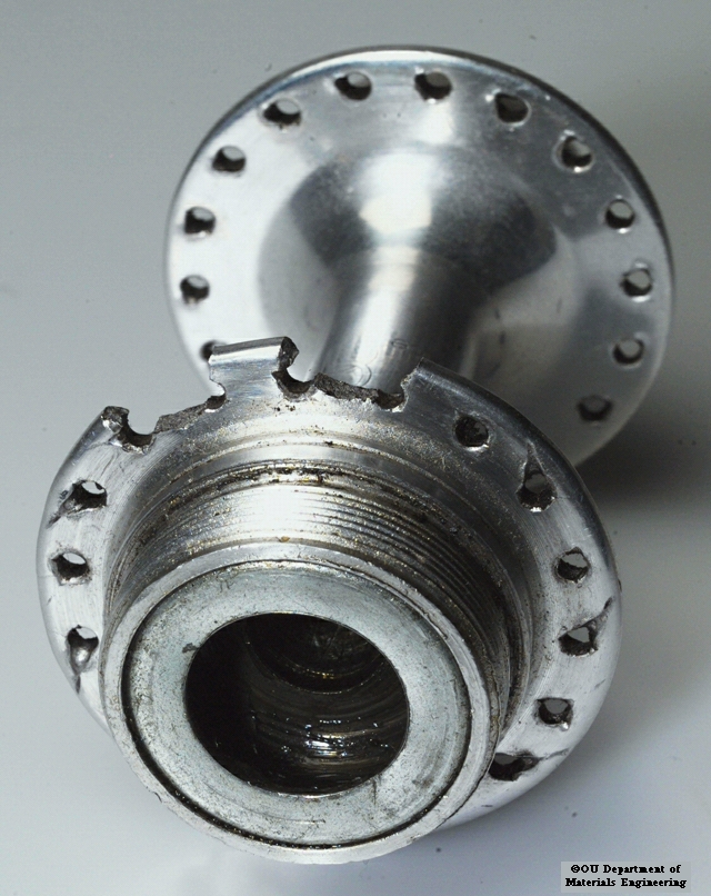
This road bike hub caused the rear wheel to collapse as 4 spokes pulled out of the hub flange. It was a fatigue failure.
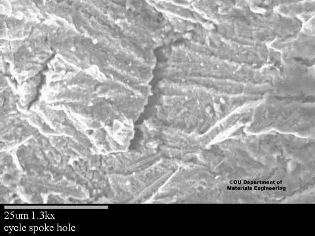
See below for two SEM (scanning electron microscope) images of the failure area.

This SEM image taken close to the spoke holes indicates that the initial crack is fatigue based due to the presence of striations. Also shown is a secondary crack.
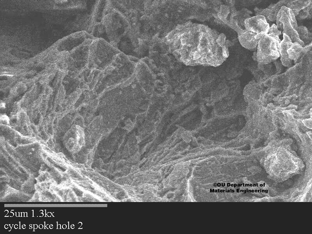
Another SEM image showing elsewhere there is ductile failure where the spokes finally pulled out of the reduced ligament of material.
From http://technology.open.ac.uk/materials/mem/mem-ccf2.html as of 2004/01.
This front brake assembly broke off under braking and severely injured the cyclist. Poor maintenance had allowed the brake bolt to loosen and allow the assembly to ``chatter'' when braking imposing cyclic loads instead of steady stress on the fastening bolt.
[[Note: even without chatter, this bolted joint is intended to use the bolt in tension, but a loose bolt forces the bolt in to bending. See www.boltscience.com for further discussion of bolted joints.]]
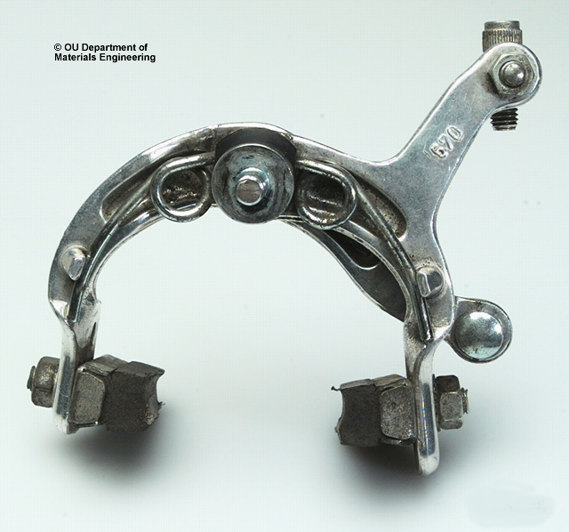
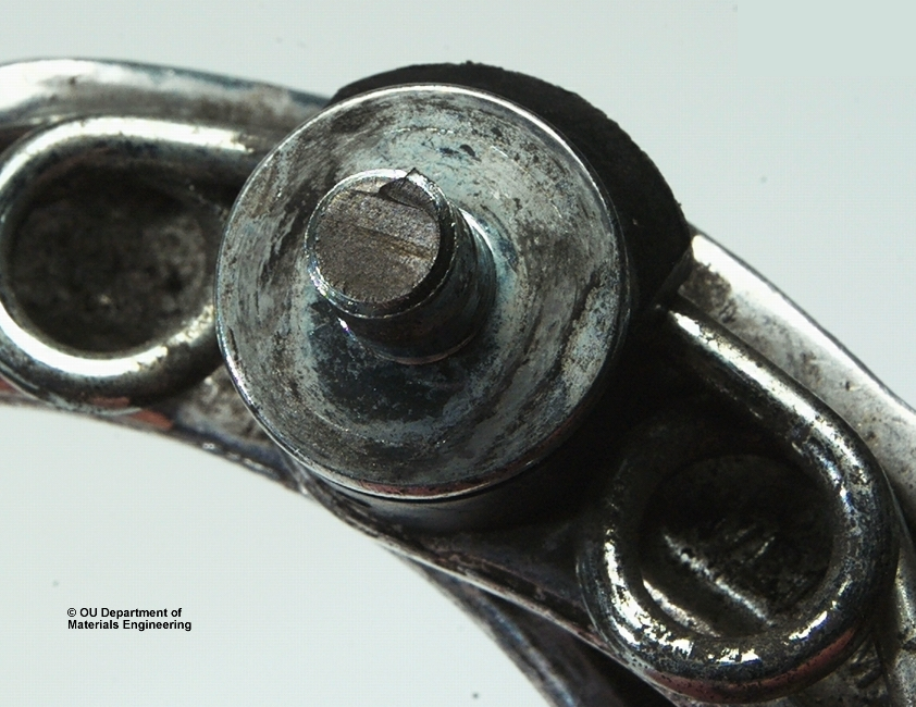
As can be seen at higher magnification the failure was caused by bending fatigue in the steel brake mounting bolt which should be firmly secured through the cycle fork.
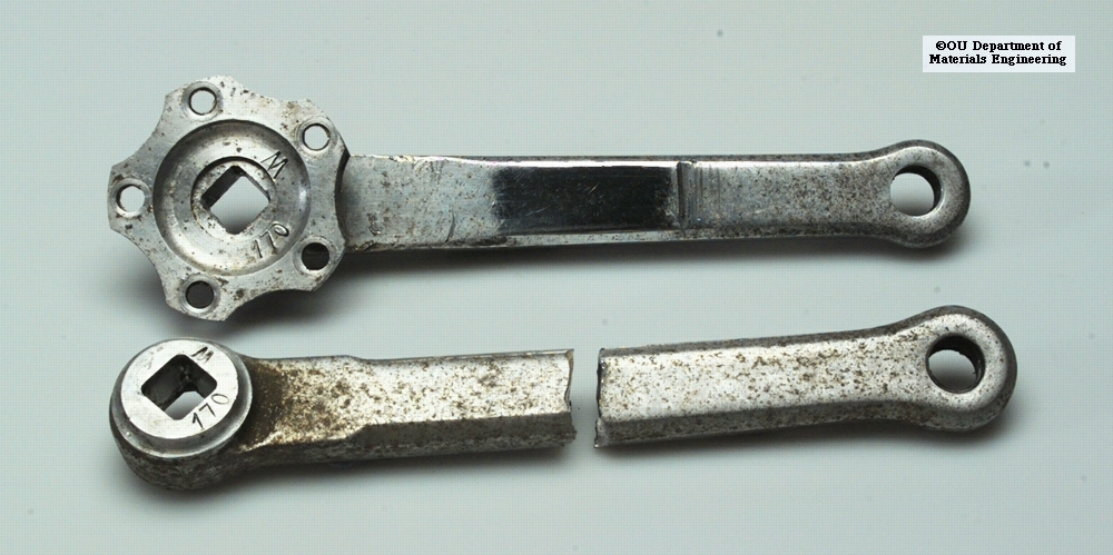
This pair of cranks have seen considerable service and have suffered severe pitting and local damage. However this did not end their life. A fatigue crack caused one crank to fail and unseat the rider.
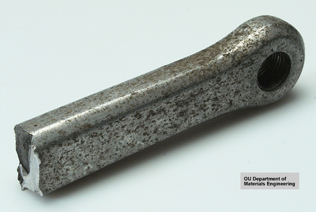
A close up showing the fracture surface shows a blackened slow growing crack that finally triggered a fast fracture. The manufacturers considered this to be an acceptable product life span and offered no recompense.
From http://technology.open.ac.uk/materials/mem/mem-ccf4.html as of 2004/01.
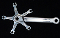
Yet another fatigue failure in a bicycle crank spider arm. This was a high quality component that had very high load cycles but was in excellent apparent condition until the final fracture that unseated the rider in heavy city traffic. Fortunately no long term injury occurred.
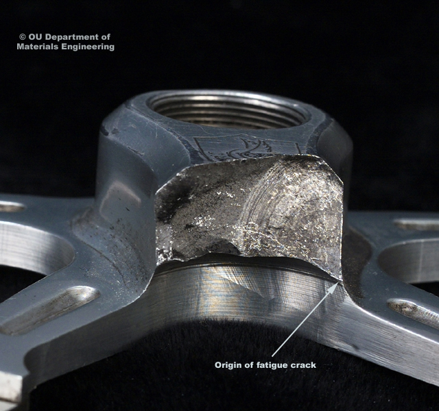
The fatigue crack initiated exactly at the location of the maximum tensile bending moment, close to the crank axle on the tensile side of the crank.
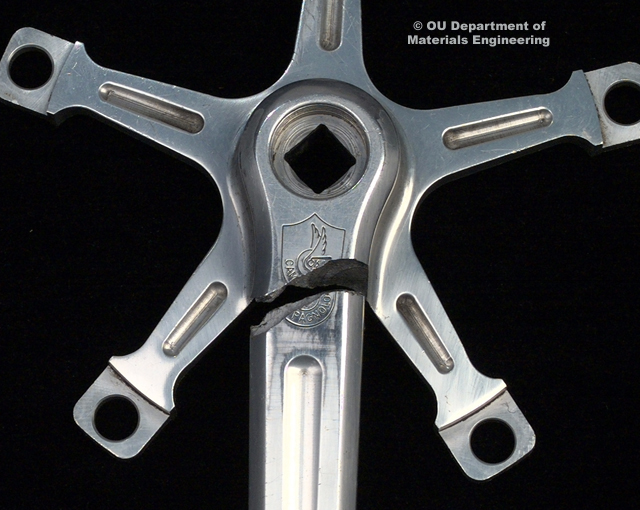
The crack progressed slowly through the crank arm (dark area) until the remaining fragment was incapable of supporting the bending moment generated by the force on the pedal and the crank arm fractured rapidly.
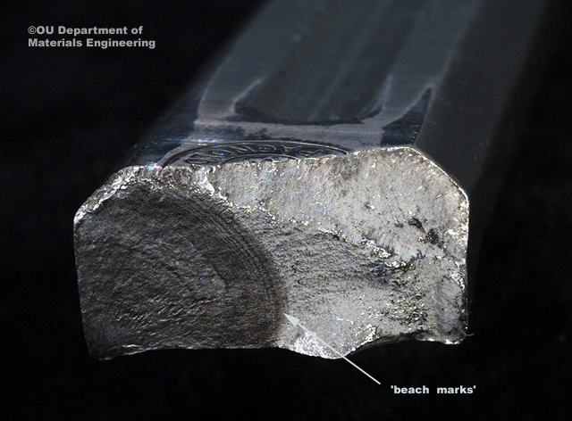
This long term fatigue crack in a high quality component took a considerable time to nucleate from a machining mark between the spider arms on this highly stressed surface. However once initiated propagation was rapid and accelerating as shown in the increased spacing of the 'beach marks' on the surface caused by the advancing fatigue crack.
This unfortunate incident may have been prevented only by very close visual inspection or dye penetrant testing (see below) on the component during the relatively short crack propagation phase.
[[Or by a different crank design with a less severe stress raiser and thus less sensitivity to machining marks, etc.]]
From http://technology.open.ac.uk/materials/mem/mem-ccf5.html as of 2004/01.
Although steel has a fatigue endurance limit certain parts of the frame are stressed above this limit and are prone to fatigue cracking. The rear triangle, comprising the chainstays and seatstays are particularly vulnerable.
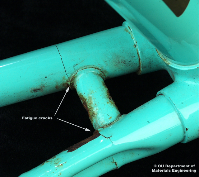
On the opposite side, the associated cracked point had caused surface corrosion. Notice that the cracks had occurred close to the brazed-on cross member. The heat affected zone associated with brazing and welding usually reduces the endurance limit and raises the chance of fatigue crack initiation
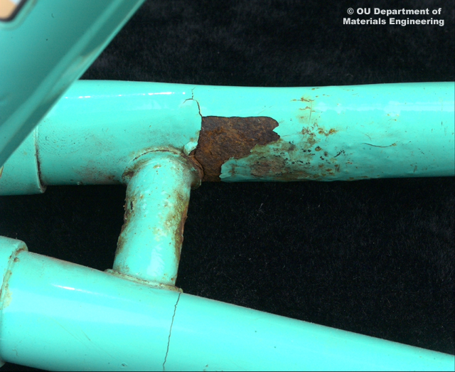
A metallurgical investigation of the extent of the heat affected zone is in progress. The manufacturers did not fulfil their "lifetime" guarantee in this instance by suggesting that damaged paintwork caused corrosion, which in turn initiated fatigue.
[[Of course it may have been instead that frame cracking caused paint damage which allowed water to enter and rust the metal under the paint. In other words, fatigue caused corrsion caused damaged paint.]]
Endurance limit (fatigue): In fatigue testing, the number of cycles which may be withstood without failure at a particular level of stress.
Heat effected zone [[sic]] - HAZ; Whenever welding, brazing and soldering is used to join metals the neighbouring parent material is effected. It may be remelted, recrystallised, annealed or stress-relieved due to the energy input. Material properties such as hardness and yield strength can be changed (usually reduced) in this region. Low energy and concentrated heat sources minimise the extent of the zone, such as electron beam or laser welding compared to gas torch processes.
From http://technology.open.ac.uk/materials/mem/mem-comp.html as of 2004/01.
Failure of Carbon Fibre Reinforced polymer (CFRP) cycle frames.
From http://technology.open.ac.uk/materials/mem/mem-comp1.html as of 2004/01.
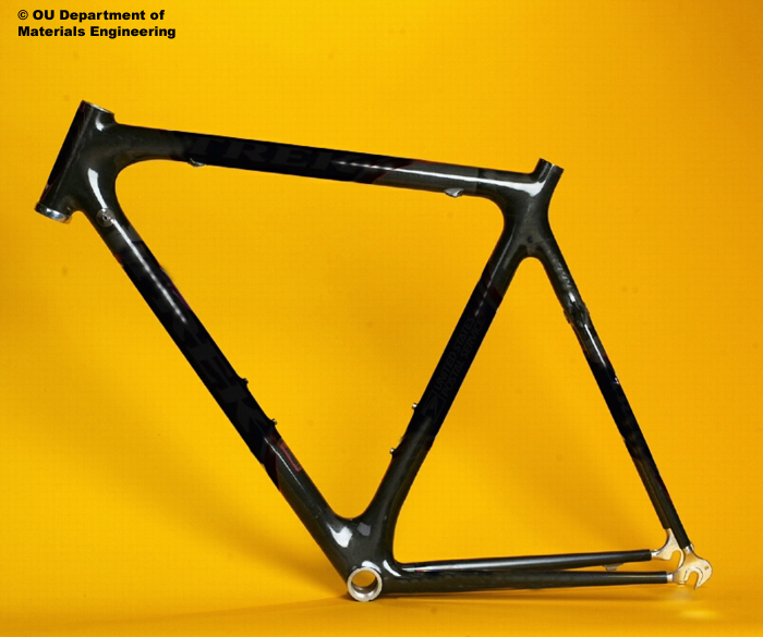
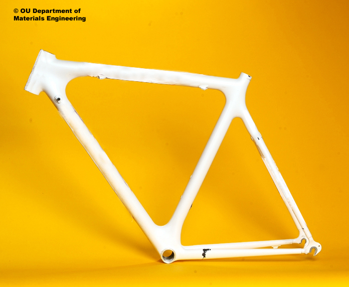
Although very strong and very stiff in theory, several catastrophic failures of carbon frames have been reported in accidents.
In some, the wheels have survived intact but the frame has failed. Many experienced riders have reported that a metal frame would have survived intact. Such damaged frames are usually replaced under warranty
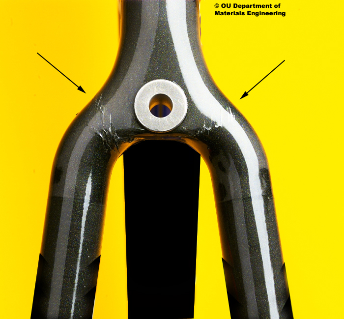
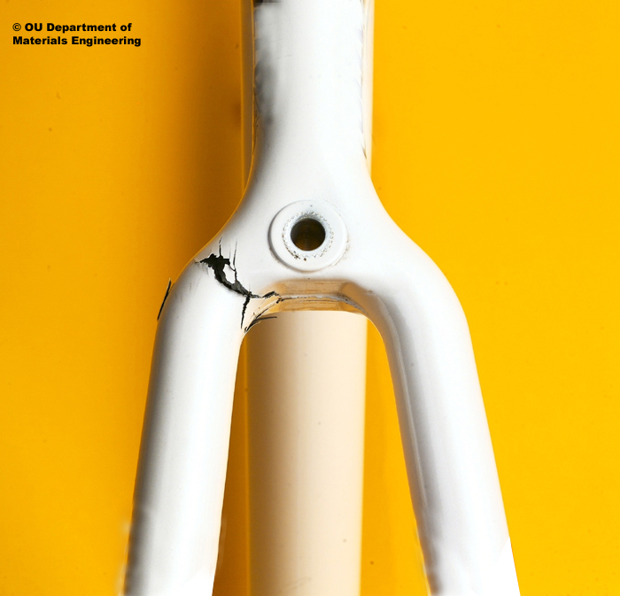
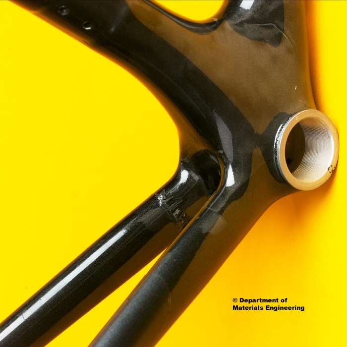
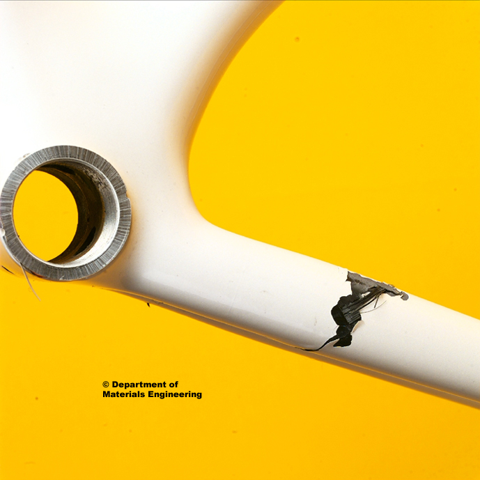
The seatstays in the vicinity of the rear brake wishbone and the chain stays appear to be the most susceptible points [[see below for why]].
Certain frames are made by joining filament wound tubes to hand made corner 'lugs' in a taper - sleeve joint arrangement where the carbon fibres are not continuous across the lap region.
Failures in the wishbone area are away from such joints but are in the hand-laid lug where material properties are unlikely to be as high as those in the automated-manufactured tube sections.
From http://technology.open.ac.uk/materials/bikeframes/bikeframe.html as of 2004/01.
[[Stiffness often affects failure, however strength and durability are apart from stiffness. Page omitted from this summary.]]
From http://technology.open.ac.uk/materials/mem/mem-ccf-rims.html as of 2004/01.
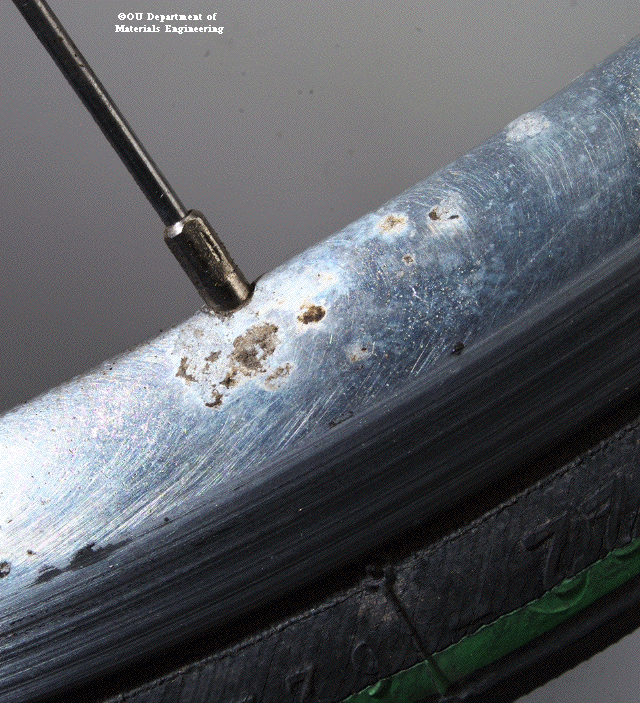
This polished aluminium rim was left over Christmas with road salt and mud on the rim. Galvanic corrosion has started between the chromium plated brass spoke nipple and the aluminium rim.
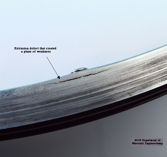
This extruded section cycle rim contains an extrusion defect that created a plane of weakness. When the wheel was being rebuilt with new spokes the increased tension ruptured the rim.
[[Note also the machining marks left over from manufacturing, which may have contributed stress risers.]]
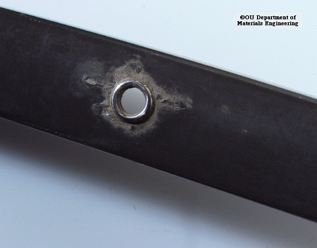
Galavanic corrosion can be even worse underneath the tyre in cycles used all winter. Here the corrosion is so advanced it has penetrated the rim thickness.
From http://technology.open.ac.uk/materials/mem/mem-ccf6.html as of 2004/01
This lightweight titanium alloy cycle seat post lasted only 500m before failure of the seat rail clamping mechanism caused the seat to tilt forwards. The hinge mechanism required three cylindrical sections to be welded to thin plates as shown.
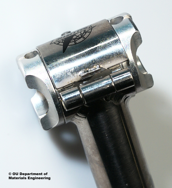
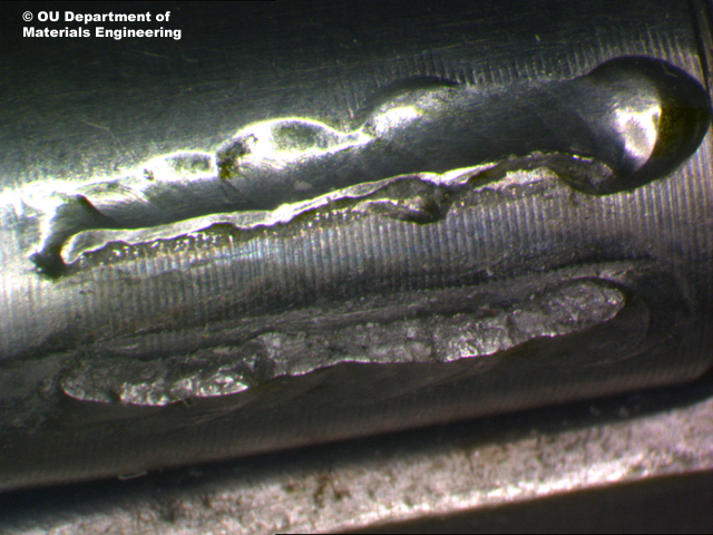
A microsection through the weld revealed that where penetration was present it appeared metallurgically sound.
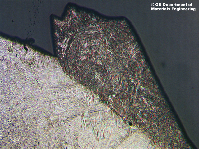
However the shape of the unpenetrated region was that of an internal notch. This shows the side of the weld next to the thicker walled hinge cylinder. Even there the fracture event had nucleated a sharp crack in the corner of the weld penetration defect.
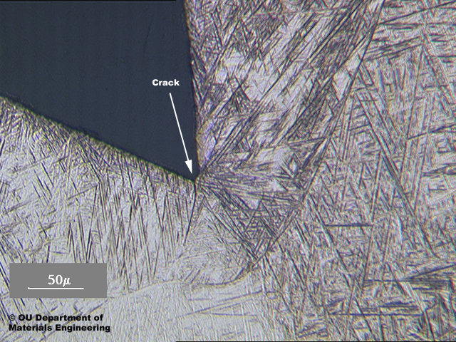
The component had a manufacturing process that included a very poor design and an unacceptable welding procedure. Several indentical failures were reported to the importer and the seat post was withdrawn from sale.
From http://technology.open.ac.uk/materials/mem/mem-ccf7.html as of 2004/01.
This aluminium alloy mountain bike seat post failed at the point where it entered the steel frame. It had been machined to size and the rider had marked the preferred height setting with PVC tape as shown.
The combination of the damp conditions under the tape, the machining marks and the galvanic cell produced from the aluminium seat post and steel frame caused reverse-bend corrosion fatigue to occur that enabled a crack to nucleate and grow so that the remaining ligament could no longer support the applied load.
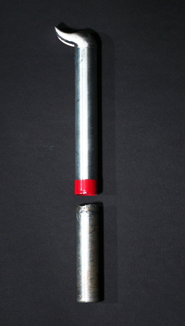
This photograph shows the machine marks on the outer surface and to the rear of the photo the ductile failure as the last material fractured.
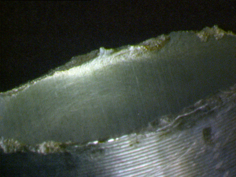
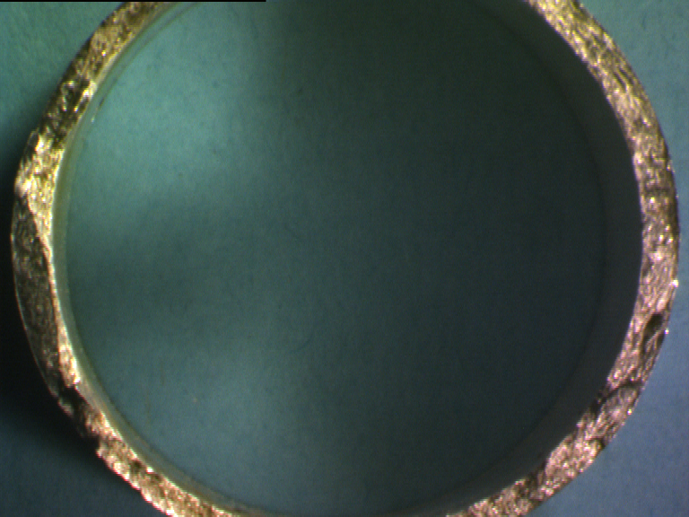
The plan view of the fracture surface shows the half moon corrosion fatigue crack at 9 o'clock and the fast fracture surface it triggered.
From http://technology.open.ac.uk/materials/mem/mem-dye-2.html as of 2004/01.
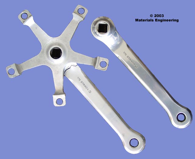
The crank spider arm of this chainset fractured and unseated the cyclist in heavy city traffic.
It was old but well looked after and cleaned regularly The growing fatigue crack was undetected until the dangerous failure. The cyclist was concerned if a similar crack had been nucleated in the matching plain crank arm shown alongside.
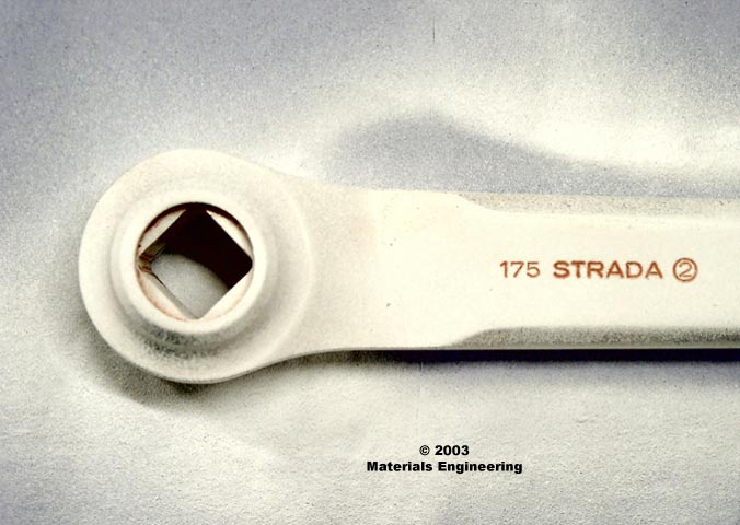
The equivilant area was sprayed with red penetrating dye which was then left to soak into any cracks or fissures in the component. After several minutes of soaking the dye was cleaned off the components surface.
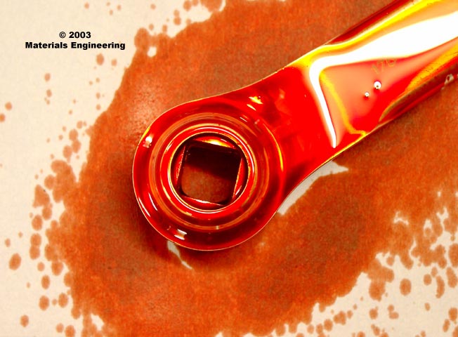
The pre-soaked and cleaned area was then sprayed with developer spray which is basically chalk powder in a volatile carrier. Any defects present show up as the red dye is pulled out of any cracks or fissures in the component. It was concluded that none were present . The only red marks were from dye that had been retained in the stamped product identification marks.
