See other failures under 000.html.
Bicycle parts are built to be light weight. Parts which give reliable service are often considered ``overbuilt'' and are redesigned to save a few grams. The goal of designers seems to be to make every element of the bicycle be ``the weakest link in the chain.'' That is, no grams should be ``wasted'' making anything durable. If a crank breaks at the ends but not in the middle, then the middle is clearly overbuilt and should be reduced. As a result, all elements of most parts are thus highly stressed.
Failures are often both interesting and difficult to understand: each failure is rarely from a simple design flaw, but is more often is the result of several factors working together. For example, microscopic motions in a joint may wear one part; the wear debris is then pushed around, which in turn damages the wearing part, causing it to fail. Thus, while the part may be more than strong enough to resist the basic load, it breaks anyway. Fixing or avoiding failure-prone designs needs an understanding of the whole failure process.
A further issue is that bicycle parts are built and sold with little design and testing. ``New'' usually means ``poorly-tested''; but even established designs can be failures waiting to happen. As a result, ordinary cyclists often wind up buying parts which appear adequate but which soon must be replaced or which injure the rider. Ordinary cyclists are thus often interested in how and why failures occur.
Note, by the way, that the approach of ``trim away anything which is durable'' may lead to a part which is light given the design, but a different design may be both lighter and more durable. For example, parts may be built to withstand the effects of abrasion from wear debris; a joint which has less motion produces less debris, and so can be built lighter.
The following are some examples of bicycle parts, failures, and in a few cases designs which seem like they ``ought'' to be poor, but which work well in practice. These exaples are presented in order that you can better understand bikes, and in doing so make choices which help you better enjoy cycling.
Some things work even though it seems like they ought to fail. Here is one example. This working design suggests a similar design that is not currently used -- likely because it fails.
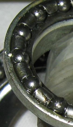
The following picture shows part of the internals of an inexpensive Regina freewheel. There are only a few bearings, and the remaining space is filled with long spacers. The spacers are simply pieces of wire bent to fit in the space that would otherwise be filled with bearings. Bearings are expensive, bent wire is cheap.
Using wire spacers means that only a few balls support the freewheel. However, they are adequate, as loads are small when the freewheel is coasting. The bearing loads are much higher under pedaling, but the motion between the two freewheel parts is likely large enough to allow lubricant replenishment. Probably the biggest downside of the few balls/large spacers approach is increased coasting drag.
![[img_0162.crop.jpg]](img_0162.crop.jpg)
Since a small number of balls is adequate, that suggests that a plain bearing (bushing) would also work well. However, freewheels are commonly subject to dirt intrusion and lubricant wash-out. A rolling-element bearing can keep working when dry and dirty, but a bushing might fare poorly. At least one plain-bearing freehub (American Classic?) was marketed, but it is no longer available even though plain bushes should be both cheaper and lighter than balls.
As an aside, note that ceramic bushes, such as are used for some derailleur pulleys, are harder than most grit and thus tolerant of grit. When lightly loaded, they can also run without lubrication, thus reducing the amount of grit drawn in and trapped in the bushing. They may be acceptable.An inexpensive headset, with spacers to reduce the number of bearings. Headsets are often damaged (``dimpled'') by fretting (false brinelling) caused by loads which displace lubricant and which are too small to replenish the lubricant. Since headset bearing failure is already common, further reducing the number of headset bearings is probably a poor choice, even though it works effectively for freewheels.
A newer-style ratchet ratchet -- instead of a wire segment directly lifting the underside of the pawl, a single ``clasp'' spring constricts all pawls; an eccentric motion lifts the pawl.
The clasp-spring pawl has several advantages compared to a direct-lifting pawl: it stays together during assembly, whereas the earlier design tends to fall apart during assembly; the clasp-spring pawl is stronger; it has a larger bearing at its heel, so it is more durable; and it is quiet. Nearly all modern pawl-type ratchets use a clasp-spring pawl.
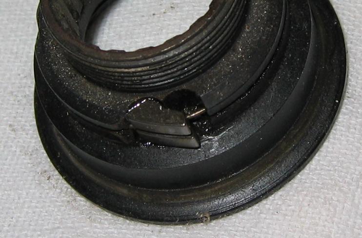
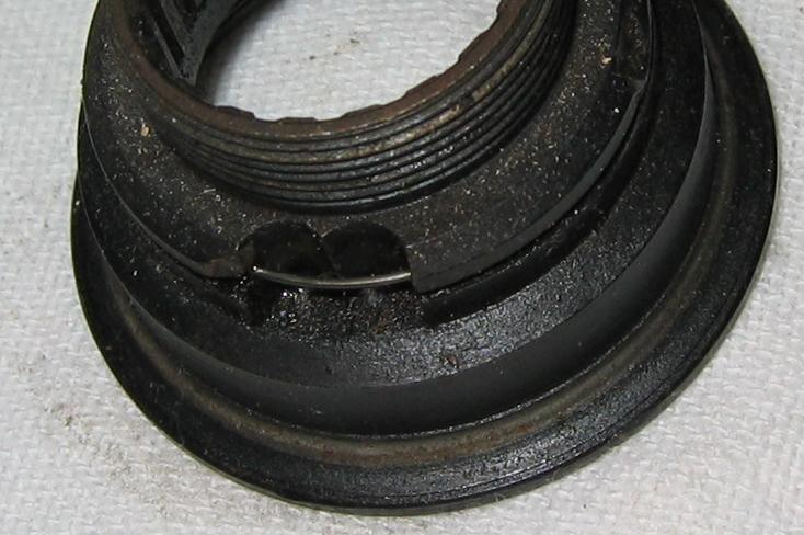
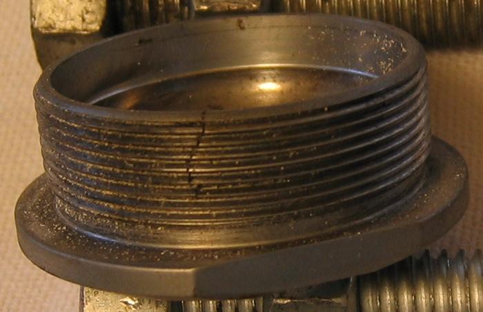
An older Shimano Dura-Ace headset with an aluminum cup and a fixed-position hardened-steel bearing race insert. Note that newer Shimano headsets use an angular-contact bearing cartridge where one race has a spherical contact to the cup, allowing cup/race motion for motions the ball elements are not able to handle.
This headset's crown race has a coating, probably titanium nitride. The coating is largely worn away in the ball track. The crown race is badly pitted (not shown) [Take new picture.]. It appears to be a grit-type failure rather than a false-brinell (fretting) failure.
There is a very close-tolerance labyrinth seal. The type of failure and the presence of contaminants suggests the seal was inadequate. Note that tight-tolerance labyrinth seals can ``wick'' materials past the seal, where a larger-clearance labyrinth does not. However, large-clearance labyrinth seals may fare worse against a pressurized stream of contaminants. In the absence of further shielding, the headset's lower race is in the direct path of a stream of dirty water thrown from the tire.
![[img_0163.crop.jpg]](img_0163.crop.jpg)
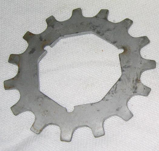
A [?brand?] sprocket with an octagonal spline.
A disadvantage of the octagonal spline is that it generates a larger hoop stress than a conventional spline.
An advantage is that the sprocket tends to wedge in place under load, thus reducing motion between the sprocket and the carrier. A spline with nearly-radial faces, such as the spline on Shimano freehubs, tends to load spline teeth in succession. As a result, the sprocket can move under load. Some freehubs creak under load in some gears due to motion between a sprocket and the carrier. The creaking indicates motion, wear, and failure at a much lower number of load cycles.
Threaded sprockets tend to creep under load. If the left sprockets use a right thread, they will tend to self-loosen. If left-threaded, the large-diameter thread and fine pitch means the sprocket will self-tighten until it is very difficult to remove.
The sprocket is [?]-threaded.
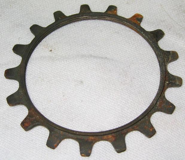
A sprocket may lose one or many teeth and still be entirely rideable. It may be difficult to notice missing teeth without visual inspection.
Although missing teeth increase some tooth and chain loads, the increases are only modest, as most load is already carried by a single tooth at any given moment.
Note the 13T sprocket has another tooth starting to break off.
![[img_0170.crop.jpg]](img_0170.crop.jpg)
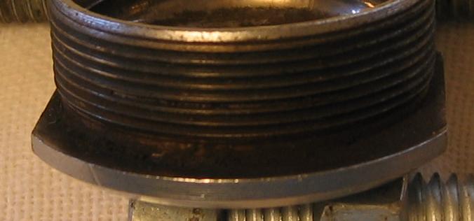
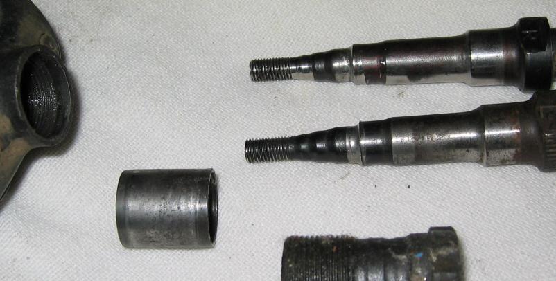
A Campagnolo spindle for a quill pedal. The right thread is relieved where it meets the axle. An earlier model was not relieved and transitioned directly from the threads to the larger-diameter spindle. These reportedly broke more often.
![[img_0171.crop.jpg]](img_0171.crop.jpg)
![[img_0171.crop2.jpg]](img_0171.crop2.jpg)
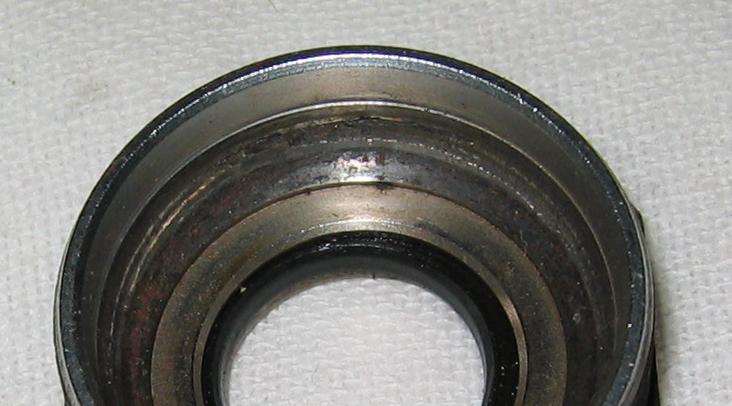
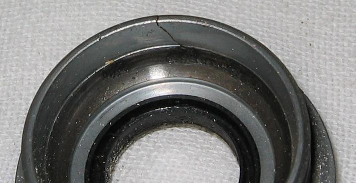
A right-side Campagnolo bottom bracket cup. The first picture shows a damaged section of the race; the damage includes a fracture which goes clear through the cup to the root of one thread, shown poorly in the second picture.
This cup self-loosened and backed itself out of the frame several turns leading to a loose bottom bracket.
The cup lasted 15 years at about 15,000 km (10,000 miles) per year. It was not obviously damaged the last time a crank spindle was replaced (about 1-2 years prior).
An [?Avocet?] fixed cup with a through crack between race damage and the edge of the cup.
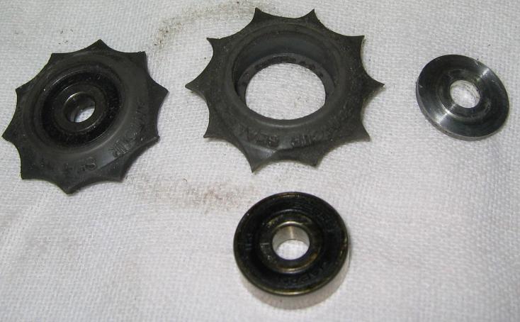
SunTour plastic jockey pulleys using cartridge bearings. The teeth are worn away but the bearings turn freely.
Many other brands of cartridge-bearing pulleys (Bullseye, Control Tech, etc.) use similar cartridge bearings. When used in poor weather, many other brands become too damaged to use after only a few months use. The same riders often get good service from SunTour pulleys. An obvious construction difference is the SunTour pulleys use a pair of aluminum ``spacers'' which may also act as labyrinth seals.
Plain-bush bearings seem far more durable, though they arguably have worse friction. Ceramic-bush bearings, used in some Shimano derailleurs, are designed to run without grease. The ceramic is harder than most grit, the lack of grease helps keep the bushing from attracting more grit, and the bushing is lightly loaded. Many riders get good service from these ceramic bushings,, and the ceramic bush also spins freely when unloaded, suggesting low loaded friction.
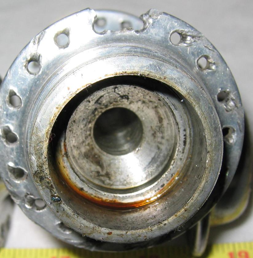
Hub flange fracture. Fractures are more common when a wheel is radially laced, as there is less material to support the spoke load.
This hub has been re-laced at least once -- note that every hole is indented by a spoke.
Note the bearing cup is missing -- on some Campagnolo hubs, the cup is a replaceable element.
Tubular tire -- no carbon black. These tires had marginally lower rolling resistance than a similar tire with carbon black in the rubber. However, they also had much worse traction in the wet.
Valve stems sometimes tear out of tubes. The following picture shows two failed stems. They are as-removed; note the small contact area between the stem and tube.
A torn-out stem can often be replaced with a nutted valve stem, shown on the right. Note the ``head'' of the stem has a relief and the washer is stepped, so there is a ring of contact rather than contacting all the way to the center. Note also the nut is shaped to better fit the rim. Nutted stems used to be common on tubular tires.
Valve cores can fail. Some Presta valves have removable cores. Shown are two, note the wrench flats on the valve cap threads.
![[presta006.crop.jpg]](presta006.crop.jpg)
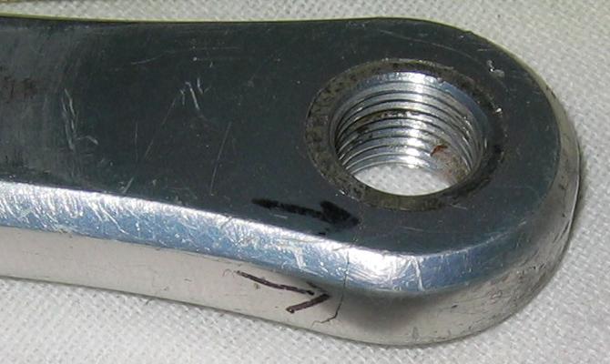
Cranks sometimes fail. Typical failures are at the pedal eye, where the chainring spider attaches, at the square taper, and at any embossing, sudden changes in section, and so on.
Although crank failures are far less common than, say, flat tires, they are nonetheless dangerous: if you are standing on the pedal and it suddenly loses support, you are likely to be thrown to the ground and perhaps out in to traffic or down the drop-off next to where you are riding.
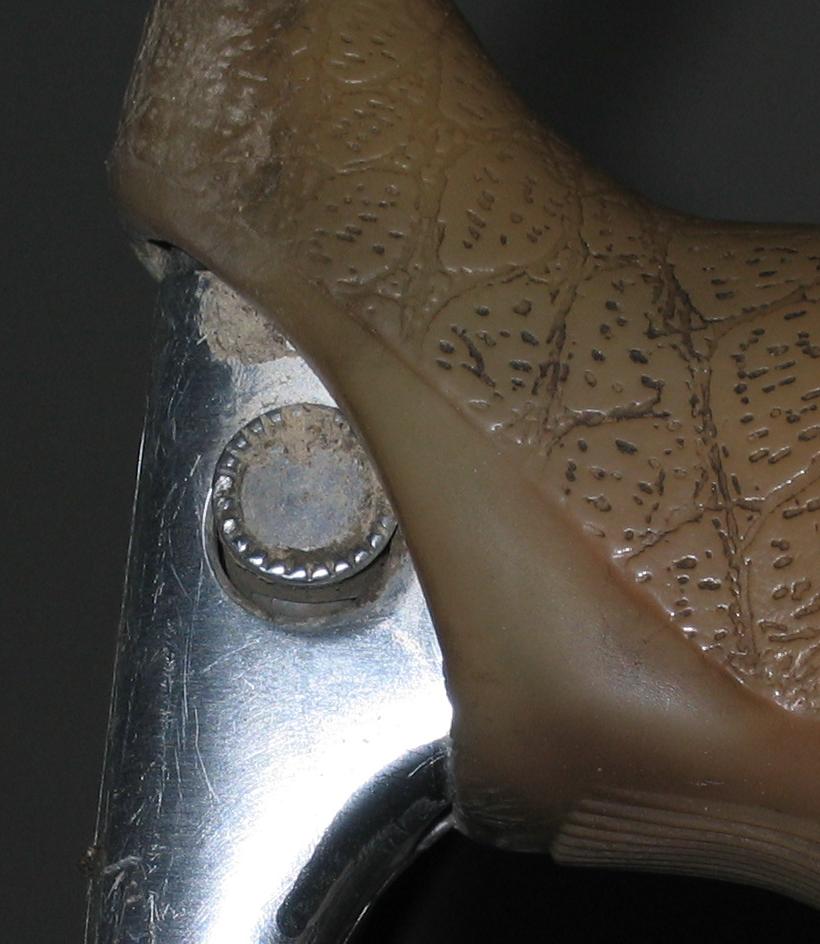
One type of pedal eye failure is a fracture on the ``outside'' face. This example is a Shimano Dura-Ace crank (FC 7402), it uses a square taper and has a solid cross section (these features do not affect the failure but help to identify the vintage of the crank).
Note that the pedal shoulder has abraded (worn) a depression in the face of the crank. This is abrasion, as the crank face was initially flat [picture] and simply installing and tightening the pedal then removing it shows no indentation. Thus, any indenting which occurs with the pedal in place is the result of motion; motion wears away at the crank.
Motion occurs here beceause the interface is poor between the crank and the pedal. Even a very tight pedal will nonetheless move under load.
Note the location of the crack. All else equal, the crack should appear at the point of highest stress. The crack here corresponds to the bottom of the pedal stroke.
Motion in the pedal/crank interface can be reduced by milling a 45-degree conical relief in the pedal eye, and then putting a tapered collet-type clamp around the spindle picture. A similar effect could be achieved by manufacturing the pedal spindle with a taper.
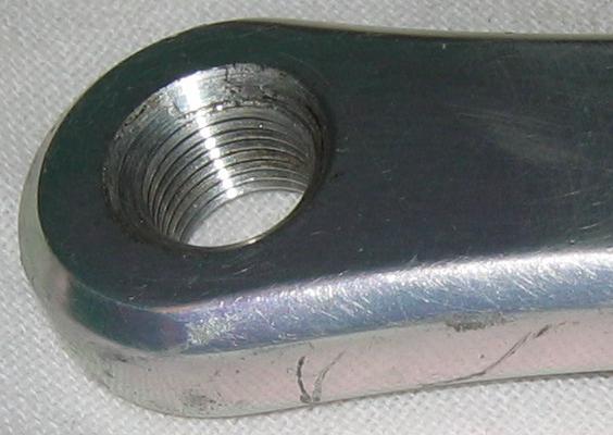
The taper reduces face motion. The threads make a corresponding taper on the back side of the crank, but the angle is steeper (60 degrees).
This crank was used extensively before being modified. It ultimately failed, but the failure may be from to earlier service without the taper and collett. The modified crank did last longer than typical for the rider.
Note the eye failed even though the crank was damaged elsewhere by rubbing on the derailleur cage.
Note also the orientation of the cracks, again suggesting a peak load near the bottom of the stroke.
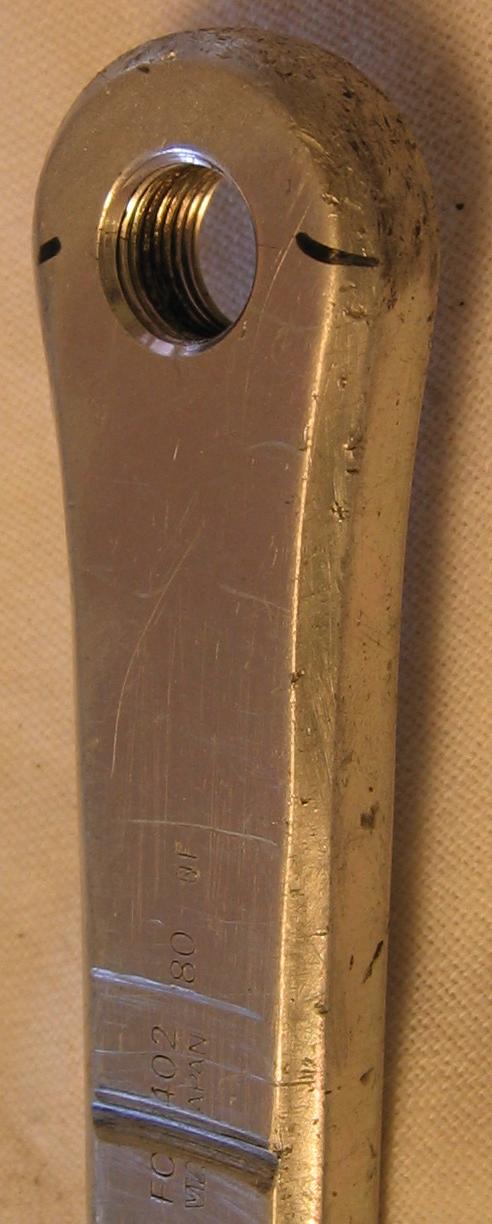
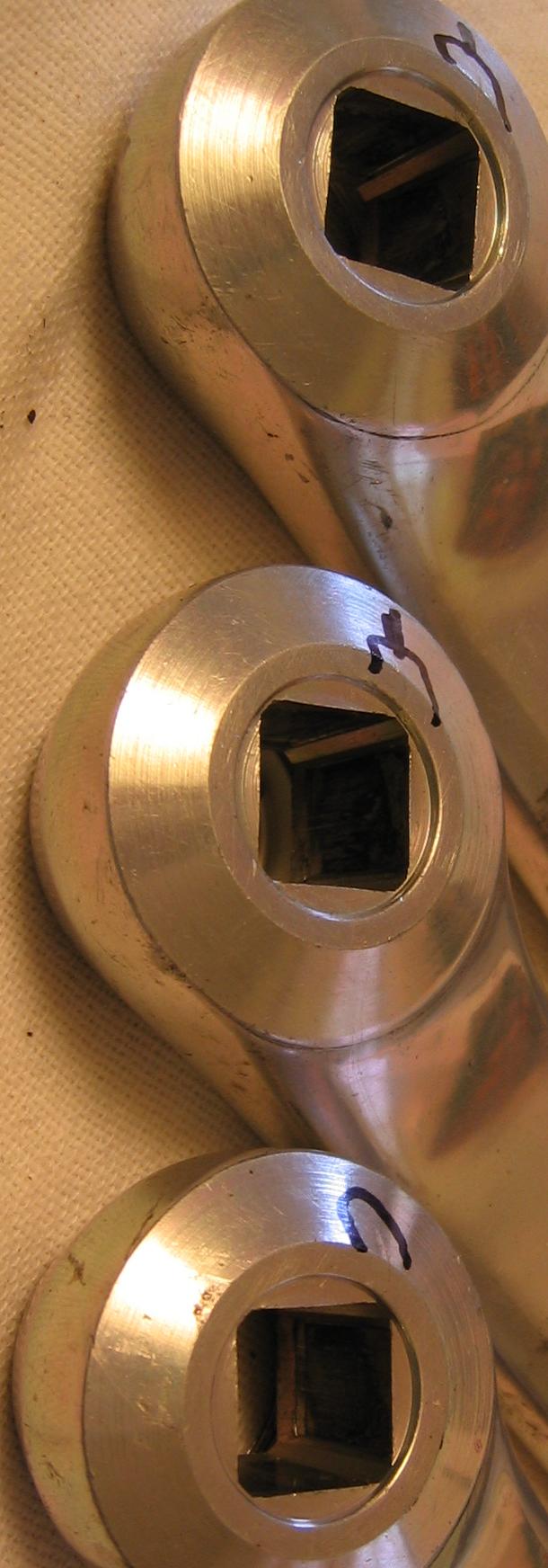
Another point of failure is the square taper. These are all FC-7402 180mm cranks ridden by a 75gkf rider with no ``granny'' gears and ridden in mixed and hilly terrain.
Several cranks failed in the same place, suggesting a design problem with the square taper rather than a material defect in one crank.
Crank spindles have bearing failures, likely due to the combined effects of grit intrusion, spindle flex, bearing misalignment, and bearing loads caused by poor bearing geometry.
The issue of bearing geometry may not be obvious. Consider a radial load on an angular-contact bearing. Since load is not carried directly across the bearing contacts, the bearing acts like a lever to increase the force on the bearing points. For a bearing where the contact is 45 degrees off the load path, the bearing point loads are about 30% higher than for a bearing where the contact points are in line with the load.
![[conventional.xfig.jpg]](conventional.xfig.jpg)
Spindle flex and bearing misalignment also hurt bearing life. When bearing alignment is always good, a given size of bearing can be designed to take a higher load. Conversely, where spindle alignment is relatively poor, the bearing must be designed to tolerate misalignment, but that reduces the load-carrying capacity of the bearing.
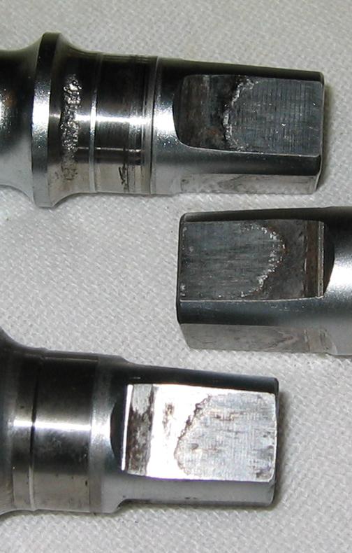
More than the bearing surface is damaged in use: the surface finish of the taper has been abraded away. The damage is from motion in use. Note that simply installing, tightening, and then removing the cranks does not abrade the surface. Since the damage is not from installation, it must be from use. Note that aluminum oxide is hard, is a good abrasive, and is generated by wearing of an aluminum crank.
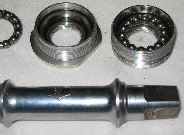
A Campagnolo bottom bracket with aluminum cups and race inserts. A conventional design uses one piece of metal as both the cup and the race. Since the cup+insert is thicker than the conventional design, the bearing size must be reduced.
Although this unit has not yet failed, it is likely that it would fail faster due to the smaller bearing sizes -- smaller bearings bend more sharply where they contact the race, and create a smaller contact to distribute the load and thus have higher point loads. Going to a larger number of balls does increase the number of balls to wear and to distribute the load, but the improvement is probably not as much as the durability losses due to point load problems.
Note that a different spindle is required than the conventional spindle. Note in particular the deeper shoulder next to the right spindle race.
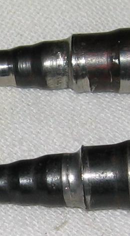
The bearing race on the pedal spindle has been deformed due to use of relatively soft metal. A harder metal would fracture before it would deform this way.
Sometimes a gradual failure sooner is preferable to a sudden catastrophic failure later. For example, a spindle fracture might leave the pedal suddenly unsupported, throwing the rider to the ground.
Stems and seatposts seize in the bike when the surface oxidizes. The oxide is slightly larger than plain aluminum.
Oxide formation is encouraged by motion between the parts. Motion is common because the parts are only clamped at one end.
Removing a stuck part may mean sawing it off then griding away at the aluminum until the hoop compression is relieved and the part can be removed.
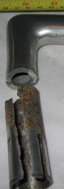
Quill stem motion can be reduced if the top and the bottom of the quill are clamped. The top can be clamped by slotting it and placing a band clamp around it. The wall thickness of the top slotted section is necessarily thin, as it can be no larger in diameter than the root diameter of the headset threads.
On this fork, the clamp section broke off, after about 225,000km riding by a 75kgf rider with riding in mixed and hilly terrain and no ``granny'' gear and thus much standing climbing.
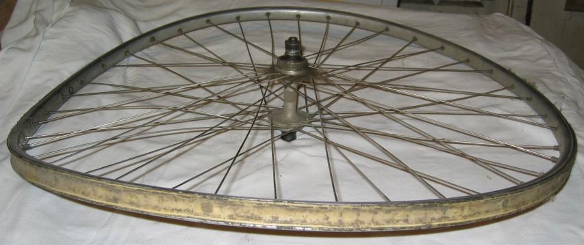
Wheel that was intentionally collapsed in a test jig, to demonstrate that a single external load can cause multiple bends leading to the classic ``taco'' shape.
the wheel was held by the axle, and collapsed by applying a single load to the rim sidewall on the far left. Note that the rim on the far right moved in the same direction as the load applied on the left.
See The Bicycle Wheel by Jobst Brandt (Avocet Press) for further explanation.
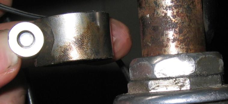
Campagnolo drop-bar brake lever. The lever has worn from a round hole to an oval at the pivot between the lever and the part which holds the cable end, due to use over several hundred thousand kilometres.
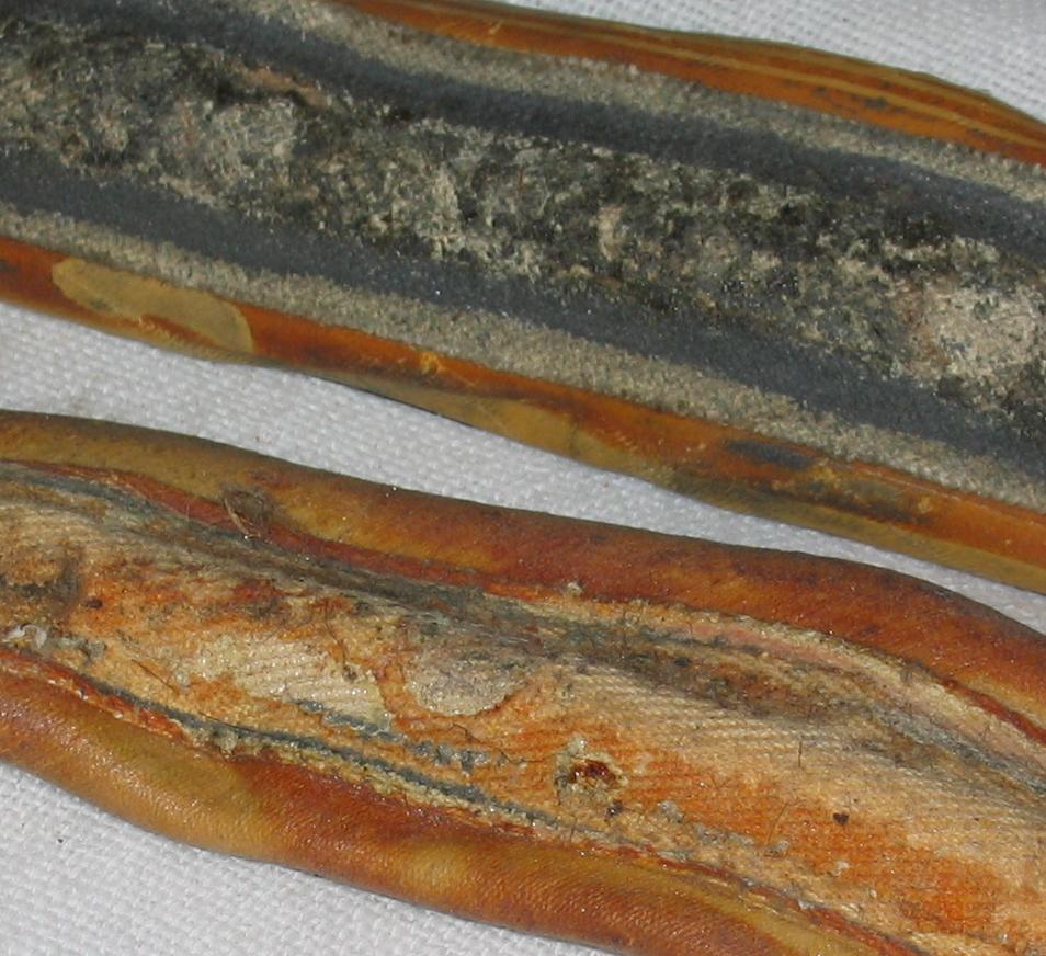
Tires rub where they meet the rim, wearing black aluminum oxide off the rim and in to the fabric of the tire. The oxide abrades the tire fabric and can sometimes cause the tire to fail at the rim before the tread wears out.
The picture shows two tubular tires, one older with more embedded oxide, one newer with less.
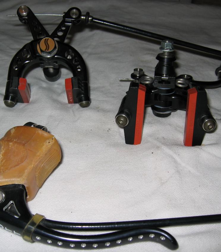
Scott ``Superbrake'' made of two identical arms running on a large-diameter pivot with plastic bushings.
The front brake cable is routed down along the lever and then to the brake. The Rear brake cable is routed normally except that it passes through an extra 90-degree bend.
The leverage from cable to pads is about the same as any other brake, and the point of highest forces for the rear brake, where the brake meets the fork or frame, is the same size as other brakes.
There is no quick-release.
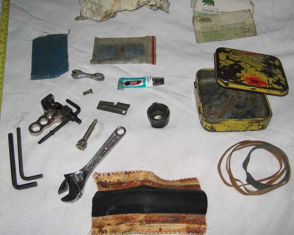
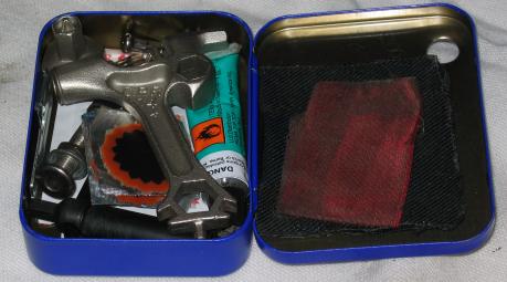
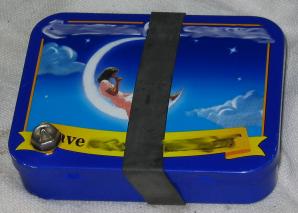
Things break on the road. Here is one tool kit, weight about 250g.
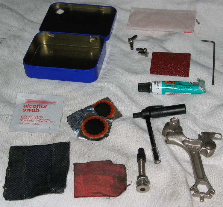
Here is another, inspired by the above. It is about 2/3 the size and weight. It lacks tools for replacing spokes under the sprocket cluster. Note two sizes of nipples for both 2.0mm (14g) and 1.8mm (15g) spokes. Not yet time-tested.
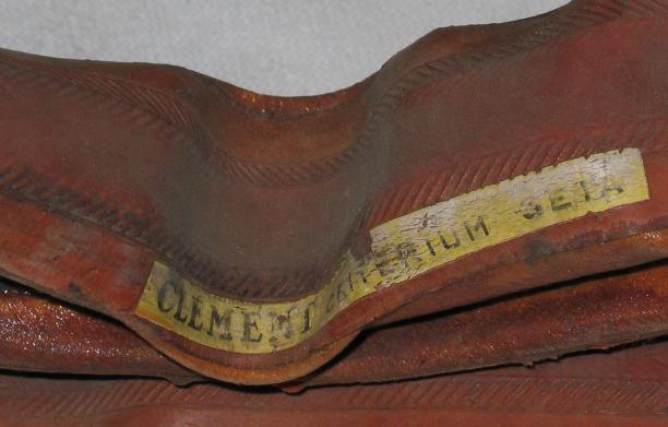
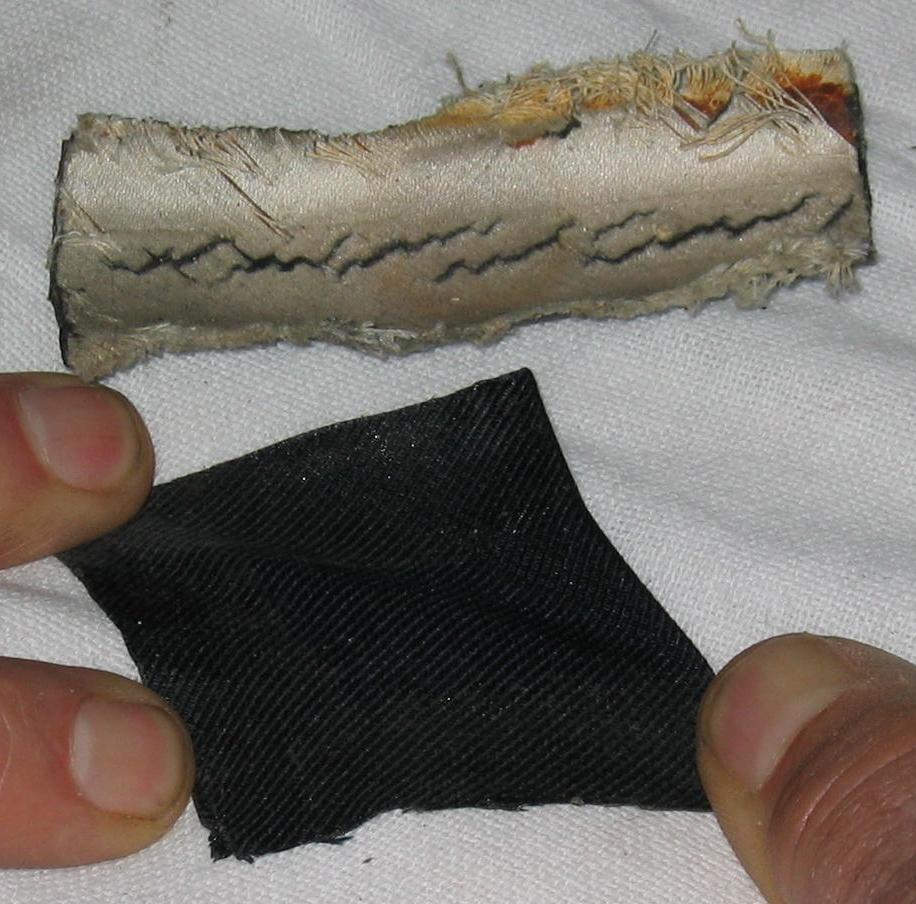
Even tools can fail. The upper item is a boot made from an old tubular tire. It shows severe tearing even after relatively little use, although some boots can be quite durable.
The lower item is a doubled piece of silk fabric being stretched to show the kind of flexibility which is needed to have a boot survive inside a tire casing.
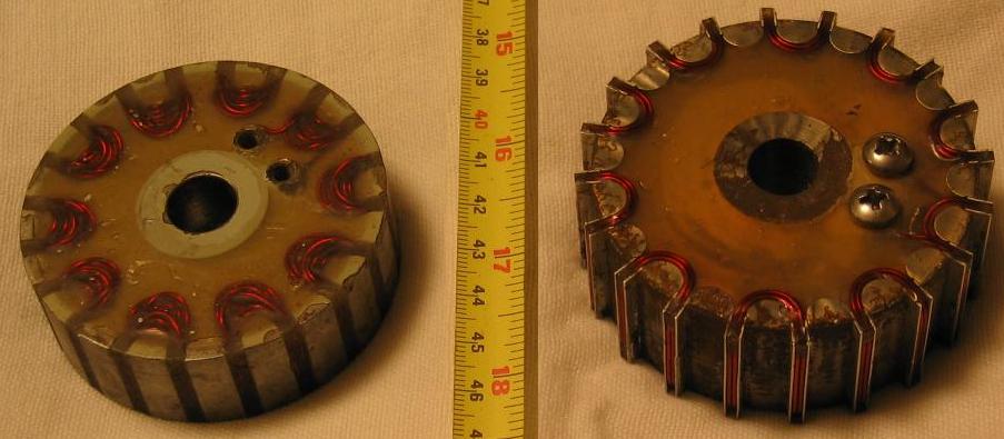
Sturmey-Archer generator hubs demagnetize the permanent magnet when disassembled, unless a magnet ``keeper'' ring is used or the magnet is removed as a unit with the moving winding. The permanent magnet may be remagnetized by applying a strong magnetic field.
The following are pictures of a remagnetizer. The magnetizer operates by charging the capacitors, then the capacitor energy is dumped through a winding placed inside the hub magnet [not shown].
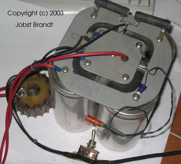
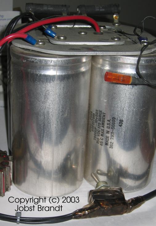
The left winding is not sufficient, as the windings must reach ``between'' the lobes of the hub magnet [not shown] to generate a sufficiently strong field.
The magnetizer circuitry is designed to be safe in the face of operation failures. When the switch is thrown, the stored energy should be dumped through the magnetizer coil. However, if the magnetizer coil is not connected, the stored energy would be a shock hazard that could last for hours. Thus, if the coil is not connected, the magnetizer is designed to dump the energy in a few seconds.
![[magnetizer-circuit-002.jpg]](magnetizer-circuit-002.jpg)
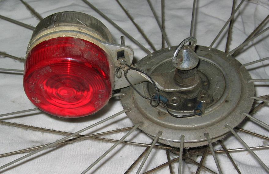
A wheel was built to swap easily between day/night utility and day-only riding with no light. Although poor for seeing, it was adequate for legal requirements.
All parts and most tools provided for photography by Jobst Brandt. Most of these components also failed in service for Jobst. All photographs taken in January 2004 unless noted.